


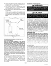
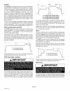

Locate the barometric draft control within 18 inches of the
furnace flue outlet, See figure 13 for barometric draft con-
trol location.
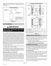
Horizontal Venting
BAROMETRIC
CONTROL*
HORIZONTAL VENT-
-- ING CONTROL
CC3
*Barometric control must be
installed in the horizontal
venting system and located
within 18" of flue outlet of
furnace.
Q U
Figure 13
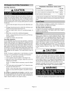
A IMPORTANT
Use 24 gauge or heavier galvanized smoke pipe and fit-
tings to connect the furnace to the vent, Connect flue pipe
to chimney using the least number of elbows and angles
possible. Flue pipe or vent connector must be inserted into
but not beyond the outside wall of the chimney flue. No re-
duction in diameter of flue pipe is acceptable. It is best to
have flue pipe as short and direct as possible. Where two
or more appliances vent into a common flue, the area of
the common flue should be at least equal to the area of the
largest flue or vent connector, plus 50% of the area of any
additional flues or vent connectors. Install a barometric
draft control (provided) and flue pipe according to instruc-
tions packed with control,
Inspect flue pipe annually. Clean soot or ash from flue pipe,
if necessary. If pipe is rusted, replace,
Install draft control at least 12 inches beyond the furnace. If
there is no space to install the draft control in the flue pipe it
may be installed inthe vent above the flue pipe, Follow the
instructions packed with the draft control,
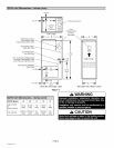
Alternate Side Flue Connections
The vent pipe may exit the top or sides of the cabinet, A
hole is provided in the top cap for top exit. For side exit, lo-
cate the center hole punched in the side of the cabinet, See
unit dimensions on page 2. Using it as the center point,
cut a 6 inch (152 mm) round hole in the cabinet's side.
Install the barometric draft control within 18 inches of the
furnace flue outlet,
Attach the provided finishing plate to cover rough edges.
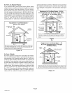
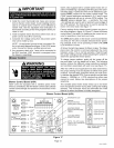
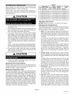
Radiation Shield Installation
COMBUSTIBLE
MATERIAL "_
UNIT t
CABINET
12" (305 ram) rain
I I
NoN_1l.
COMBUST,BLEI.,_A SEESPACERS NOTE 2 A
RADIATION SHIELDS (SEE NOTE 1)
SEE
NOTE
3
NOTE 1-Radiation shields must be constructed of 24 gauge sheet
metal minimum.
NOTE 2-Radiation shields required when A is less than 9" (229 mm).
NOTE 3-Radiation shields should extend from the top of the unit to
the top of the flue pipe.
Figure 14
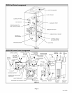
Secure return air plenum to unit using sheet metal screws,
NOTE - The following are suggested procedures that should
be followed when installing the supply air plenum,
1. Use sealing strips of fiberglass.
2. In all cases, the plenum should be secured to furnace or
evaporator cabinet with sheet metal screws.
3. Install supply and return air ducts as desired.
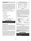
Ensure that the restrictions of the piping system, plus any
lift involved, do not exceed the capability of the oil pump,
Use the following guidelines when determining whether to
use a single-or two-stage oil pump.
One-Pipe System
When using a one-pipe system (see figure 15), even with
the oil tank that is above the burner and a vacuum of 6"
(152 mm) Hg or less, a single-stage fuel pump with a sup-
ply line and no return line should be adequate.
Manual bleeding of the fuel pump is required on initial start
up. Failure to bleed air from the oil pump could result in an
air lock/oil starvation condition.
NOTE - As an extra precaution, cycle heating on and off
ten times after bleeding air from the oilpump. This will elim-
inate air in the gun assembly.
Page 10
505082M 10/05