


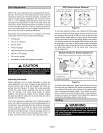
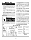

IMPORTANT
2, Install the room thermostat and make wire connec-
tions to the fan control board. Avoid installing thermo-
stat on an outside wall or where it can be affected by
radiant heat, Set the adjustable heat anticipator on
thermostat according to the wiring diagram sticker pro-
vided on unit,
3, Install a separate fused disconnect switch near unit so
power can be shut off for servicing,
4, Complete line voltage wiring from disconnect switch
near unit to make-up box.
NOTE -An equipment ground screw is provided. Re-
fer to unit wiring diagram and figure 18for 023V series
units. Ground unit using a suitable ground wire.
5, Any accessory rated up to 1 amp can be connected to
the EAC terminal. (EAC terminal is energized when
the blower is operating,)
_WARNING
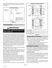
Blower Control Board (A54)
O23V units are equipped with a variable speed motor
which is controlled by the A54 blower control board. Blower
control board settings and operation are described in this
section,
O23V units equipped with a variable speed motor are ca-
pable of maintaining a specified CFM throughout the exter-
nal static range. A particular CFM can be obtained by posi-
tioning COOL jumpers on the blower control board. The
COOL jumper selections are labeled A, B, C and D; each
letter corresponds with an air volume (CFM) setting. The
ADJUST jumper is labeled Test, -, +, and Norm. The + and
- pin settings are used to add or subtract a percentage of
the CFM selected. The Test jumper is used to operate the
motor in the test mode. See figure 17.
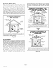
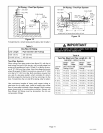
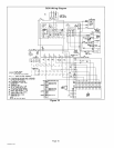
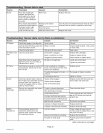
Factory settings for the blower speed jumpers are given in
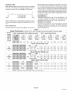
the wiring diagram in figure 18. Figure 17 shows the blower
control board. Use table 6 to determine the correct air vol-
ume for operation in heat and cool mode.
The CFM LED located on the blower control board flashes
one time per 100 cfm to indicate selected blower speed.
For example, if the unit is operating at 1000 CFM, CFM
LED will flash 10 times.
At times, the light may appear to flicker or glow. This takes
place when the control is communicating with the motor
between cycles. This is normal operation. Read through
the jumper settings section before adjusting the jumper to
obtain the appropriate blower speed.
To change jumper positions, gently pull the jumper off the
pins and place it on the desired set of pins. The following
section outlines the different jumper selections available
and conditions associated with each one (see figure 17).
After the CFM for each application has been determined,
the jumper settings must be adjusted to reflect those given
in table 6, From the table, determine which row most close-
ly matches the desired CFM Once a specific row has been
chosen (% NORMal, or -), CFM volumes from other rows
cannot be used, Below are descriptions of the jumper
selections.
The variable speed motor slowly ramps up to and down
from the selected air flow during both cooling and heating
demand, This minimizes noise and eliminates the initial
blast of air when the blower is initially energized,
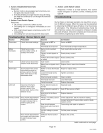
Blower Control Board (A54)
ICM PIN (_
AH4103
ARMSTRONG PIN
45632-001
PCB635-1A
R (BOARD TO MOTOR) //
c,<=co=>:::::::: //
[. C)0,: o08
D9 -E_ °JW3°'JZC]-iRr /
w,<o)o o sso ,/
0
YI I)D12 DDZ3:g: _f'_--_
G(o)0,,0,o o I LY_J
DIAGNOSTIC LED
ADJUST
/ SELECTOR PINS
/ (Setting affect cooling only)
HEATING SPEED
/ SELECTOR PINS (SEE
/ TABLE)
COOLING SPEED
/ SELECTOR PINS
j NOTE - The JW! resistor
must be cut to activate the
HUM terminal.
O23V-Q2/3-090
O23V-Q3/4-120
HEAT
..... 023V-Q2/3-070
HiO Oi
..... 023V-Q3/4-105
DI_1 O23V-Q5-140
_ O23V-Q5-154
i
HEAT SPEED SELECTOR
PINS (JUMPERS)
Figure 17
Page 13
O23V SERIES