


A CAUTION
A CAUTION
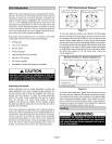
Model No.
O23V-70/90/105/120
O23V-140/154
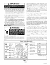
Installation of Lennox oil-fired furnaces must conform
with the National Fire Protection Association Standard
for the Installation of Oil Burning Equipment, NFPA
No. 31, the National Electrical Code, ANSI/NFPA
No.70 (in the U.S.A.), CSA Standard CAN/CSA-B139
(in Canada), Installation Code for Oil Burning Equip-
ment, the Canadian Electrical Code Part1, CSA 22.1
(Canada), the recommendations of the National Envi-
ronmental Systems Contractors Association and any
state or provincial laws or local ordinances. Authorities
having jurisdiction should be consulted before installa-
tion. Such applicable regulations or requirements take
precedence over general instructions in this manual.
Chimneys and chimney connectors must be of the
type and construction outlined in section 160 of NFPA
No. 31.
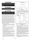
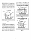
Air for combustion and ventilation must conform to
standards outlined in section 140 of NFPA No. 31 or,
in Canada, CSA Standard B139. When installing
O23V units in confined spaces such as utility rooms,
two combustion air openings are required. Dimen-
sions of combustion air openings are shown in table 1.
One opening shall be below burner level and the other
opening shall be no more than 6"(152 mm) from the
room's ceiling.
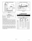
Table 1
Combustion Air Opening Dimensions
(2 openings required)
10" X 20" (254 mm X 508 mm)
11" X 22" (279 mm X 559 mm)
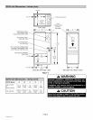
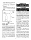
This unit is approved for use on combustible flooring
and for clearances to combustible material as listed on
unit rating plate and in table 2. Unit service and acces-
sibility clearances take precedence over fire protec-
tion clearances.
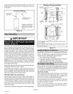
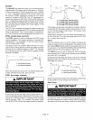
A IMPORTANT
The combustion air opening should provide a mini-
mum free area one-half square inch per 1,000 Btu per
hour input. This combustion air should be brought into
the area containing the furnace below the level of the
furnace burner.
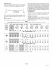
Table 2
O23V Installation Clearances
Clearances inches (mm)
top of plenum& duct 2 (51)
plenum sides 3 (76)
sides 0 (0)
rear 0 (0)
front 4 (120)
flue pipe 6 (152)
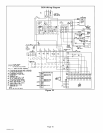
With the HEAT selector pin in the position shown in the
wiring diagram (on page 16), the unit must operate at
a temperature rise in the range listed in table 7 (on
page 17).
• When installed, furnace must be electrically grounded
in accordance with local codes or, in the absence of lo-
cal codes, with the current National Electric Code,
ANSI/NFPA No. 70, or Canadian Electric Code (CEC)
if an external electrical source is utilized.
• Field wiring connections with the unit must meet or ex-
ceed specifications of type T wire and must withstand
a 63'_F (17'_C) temperature rise.
• If installing a programmable thermostat, use a type
which retains its memory in event of a power loss.
• When the furnace is used in conjunction with cooling
units, it shall be installed in parallel with, or on the up-
stream side of, cooling units to avoid condensation in the
heating element. With a parallel flow arrangement, a
damper (or other means to control the flow d air) shall
be adequate to prevent chilled air from entering the fur-
nace and, if manually operated, must be equipped with
means to prevent operation of either unit, unless damper
is in the full "heat" or "cool" position.
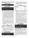
Xk WARNING
Set the unit in desired location keeping in mind the clear-
ances listed in table 2. Also keep in mind oil supply connec-
tions, electrical supply, flue connections and sufficient clear-
ance for installing and servicing unit.
Level the unit from side to side and from front to rear. Ifthe
furnace is not level, place fireproof wedges or shims be-
tween the low side of the furnace and the floor. Make sure
the weight of the furnace is distributed evenly on all four
corners. Strain on sides of cabinet causing cracking and
popping noises may occur ifweight of furnace is not evenly
distributed.
505082M 10_5
Page 4