


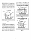

One-Pipe Systems
CAUTION
The burner is shipped with fuel pump set for one-pipe op-
eration. For one-pipe systems, the oil supply pipe is con-
nected to the inlet tap on the pump. A one-pipe system
should only be used where there is gravity oil flow to the
pump and the pipe is not run at any point above the oil level
in the tank.
1. Connect the inlet pipe to the pump inlet. Start the bum-
er,
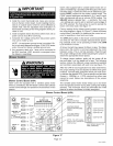
2. Arrange the primary burner control for continuous op-
eration during purging (see figure 15).
3. Turn the bleed valve one turn counterclockwise to
open.
4. Bleed the unit until all air bubbles disappear.
NOTE - Hurried bleeding will prevent the unit from op-
erating properly.
5. Tighten the bleed valve securely.
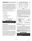
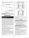
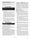
Two-Pipe Systems
If the installation requires a two-pipe operation, install the
bypass plug included in the bag which is attached to the
pump. Toconvert the pump, install the bypass plug accord-
ing to the provided pump instructions. Notice in the two-
pipe system the return pipe must terminate in the tank 3"
(76 mm) to 4" (102 mm) above the supply inlet. Ensure the
return pipe terminates at the correct measurement or air
may escape into the system. This could result in loss of
prime.
NOTE- If using an outside tank in cold climates a number
one fuel or an oil treatment is strongly recommended.
1. Remove 1/4" plug from return port.
2. Insert bypass plug and tighten it (see figure 16).
3. Attach the return and inlet pipes. Start the burner. Air
bleeding is automatic.
NOTE - If a faster bleed is necessary, open the bleed
valve.
4. The return pipe must terminate 3" to 4" above the sup-
ply pipe inlet (see figure 16).
NOTE - If the return pipe does not terminate where it
should, air may enter the system, and prime may be
lost.
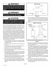
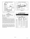
An oil filter is required for all models. Install filter inside
the building between the tank shut-off valve and the burn-
er. Locate filter close to burner for easy maintenance.
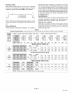
Table 5 lists the filters for the O23V furnace.
Table 5
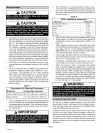
Installation Clearances inches (mm)
Oil Filters Cat. No.
10 micronfilter (no mounting bracket) 81 P89
10 micron replacementcartridge for filter,45 gph 53P93
Filter restriction indicator gauge 53P90
Consult burner manufacturer's instructions packaged with
unit for further details concerning oil supply pipe connec-
tions.
After oil piping is completed, carefully check all piping con-
nections (factory and field) for oil leaks,
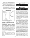
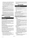
Oil Pipe Heater (Optional)
A heater for the oil pipe is available for applications that are
located in cold climates. The heater warms the oil pipe to
assist the initial start-up.
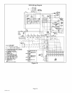
Wiring must conform to current National Electric Code
ANSI/NFPA No, 70, or Canadian Electric Code Part I,CSA
Standard C22.1, and local building codes. Refer to figure
18 for wiring diagram and to unit nameplate for minimum
circuit ampacity and maximum overcurrent protection size,
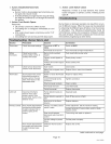
Select the proper supply circuit conductors in accor-
dance with tables 310-16 and 310-17 in the National
Electric Code, ANSI/NFPA No, 70 or tables 1 through 4
in the Canadian Electric Code, Part I, CSA Standard
C22.1.
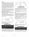
This unit is provided with holes for conduit, Reducer
washers are provided for sizing the hole to allow for
smaller conduit. Use provided caps to seal holes not
used. Refer to figure 17 for the terminal designations on
the A54 blower control board, Refer to figure 18 for unit
schematic wiring diagram with typical field wiring.
Separate openings are provided for 24V low voltage and
for line voltage. Refer to figure 1 for specific location.
WARNING
1. Refer to the appliance rating plate for proper fuse size.
505082M 10_5
Page 12