


ADJUST
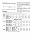
The ADJUST pins allow the motor to run at normal speed,
approximately 15% higher than normal speed, or 15% low-
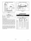
er than normal speed. Table 6 gives three rows--NORM,
(+), and (-) with their respective CFM volumes. Notice that
the normal <'NORM" adjustment setting for cool speed
position C in table 6 is 800 CFM The "(+)" adjustment set-
ting for that position is 920 CFM (115% of 800 CFM) and
the "(-)" adjustment setting is 680 CFM (85% of 800 CFM).
After the adjustment setting has been determined, choose
the remaining speed settings from those offered in the
table in that row.
The TEST pin is available to bypass the blower control and
run the motor at approximately 70% to make sure that the
motor is operational. This is used mainly in troubleshoot-
ing. The G terminal must be energized for the motor to run.
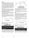
COOL (single-stage systems)
The COOL jumper is used to determine the CFM during
cooling operation. This jumper selection is activated for
cooling when Y1 is energized. Y1 and Y2 must be jump-
ered for single stage cooling.
The blower motor runs at 82% CFM for the first 7-1/2 min-
utes of each cooling demand to allow for greater humidity
removal and to conserve energy. If, after 7-1/2 minutes,
the Y demand is not met, 100% CFM is supplied until the
demand is satisfied.
Y
7.Sminutes ] 100% I 50
so(
/
i
CALL
Y - Cool Demand Present
- Cool Demand Satisfied
OFF
When the demand for cool is met, the blower ramps down
to 82% CFM for 60 seconds, then turns off.
COOL (two-stage systems)
IMPORTANT
A thermostat call for first-stage cooling closes the R to Y1
circuit on the A54 blower control board. The blower motor
runs at 57% CFM for the first 7-1/2 minutes of the 1st-stage
cooling demand. After 7-1/2 minutes, the blower motor
runs at 70% CFM until the first-stage demand is satisfied.
Y1 7N/2 YI/Y2 y2/Y1 yl
y57°/° minutes 1_i_-i°60 \y° 100°/° (_t_ I7_o 60
i sec \ i
CALL yl OFF OFF
Y1 -1st-stage COOL Demand Present
yl - 1st-stage COOL Demand Satisfied
Y2 -2nd-stage COOL Demand Present
y2 - 2nd-stage COOL Demand Satisfied
If first-stage cooling does not satisfy the demand, the ther-
mostat calls for 2nd-stage cooling, closing the R to Y2 cir-
cuit on the A54 blower control board. The blower motor
ramps up to 100% CFM
When the Y2 demand is met, the blower ramps down to Y1
at 70% CFM until Y1 is met, and ramps down to 57% CFM
for 1 minute, then turns off.
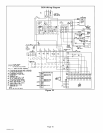
HEAT
The unit is factory-set to run at the middle of heating rise
range as shown on the unit rating plate. The jumper on the
tap marked HEAT should remain in the position (A, B, D, or
D) as shown in the HEATING SPEED SELECTOR PINS
graphic found in the wiring diagram (figure 18).
The HEAT jumper is used to determine CFM during gas
heat operation only. These jumper selections are activated
only when W1 is energized.
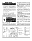
During the heat ON delay, the blower runs at 13% CFM for
the first minute, 50% CFM for the second minute, and full
CFM after two minutes.
W
60 61_
sec sec
w
100% _ _ 210 seconds
82%
\
W - Heat Demand Present
\
- Heat Demand Satisfied
CALL OFF
When the demand for heat is met, the blower ramps down
to 82% CFM for 3-1/2 minutes, then turns off.
Heat Pump
IMPORTANT
In heat pump mode, a call for heat pump operation follows
the same sequence as a call for cooling, with the exception
that there is a 30-second blower ramp-up to blower CFM
505082M 10/05
Page 14