


Page 7
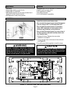
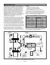
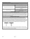
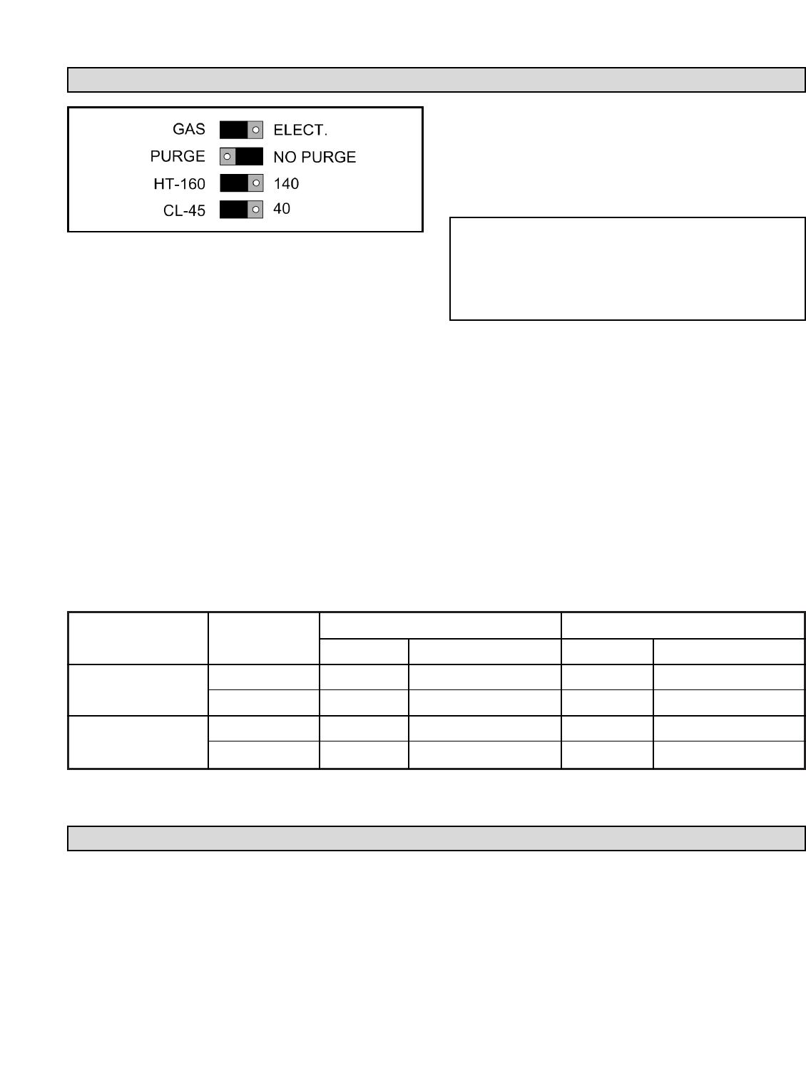
Pin Jumper Settings (see Figure 5)
LEDs
ELECTRIC/GAS: If electric heat is to be used, move the
jumper to the “ELECT” position. This will turn on the fan
(G output terminal) with a heat call (W output terminal).
If the jumper is in the “GAS” position, it is assumed that
the heating equipment will control the fan operation.
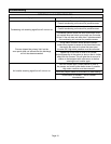
NO PURGE / PURGE: If the NO PURGE / PURGE
jumper is moved to the “PURGE” purge position, the G
terminal will remain energized for a one minute purge
delay following the completion of a cooling call. If the
jumper is moved to the “NO PURGE” position, the G
terminal will de-energize immediately following the
completion of a cooling call. The NO PURGE setting is
designed for use with systems where the furnace or air
handler has a built in fan purge. The NO PURGE
damper hold time is longer than the PURGE setting due
to the Lennox furnaces installer settable maximum
blower off delay of 3 minutes. The following chart details
the zone panel outputs and damper hold times when a
heating or cooling call is satisfied:
DISCHARGE AIR SENSOR HT-140/160: This jumper
controls the temperature at which the heating equipment
will cut out to prevent overheating. For a high limit
temperature of 140°F, move the jumper to the “140”
position. For a high limit temperature of 160°F, leave the
jumper in the “160” position.
DISCHARGE AIR SENSOR CL-45/40: This jumper
controls the temperature at which the cooling
equipment will cut out to prevent freezing the indoor
coil. For a low limit temperature of 45°F, leave the
jumper in the “45” position. For a low limit temperature
of 40°F, move the jumper to the “40” position. To
maintain optimum operation, it is recommended to leave
this setting at “45”.
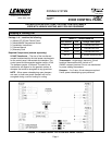
FIGURE 5 – PIN JUMPER SETTINGS
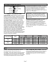
Jumper Settings Mode
Purge No Purge
Output Damper Hold Time Output Damper Hold Time
Heat/Cool
Cooling G
1
1 minute No G, 3-1/2 minutes
Gas
Heating No G 1 minute No G, 3-1/2 minutes
Heat/Cool
Cooling G
1
1 minute No G, 3-1/2 minutes
Elect.
Heating G
1
1 minute No G, 3-1/2 minutes
POWER – Blinks during normal operation. Starts to
blink approximately 6 seconds after power up.
G, Y and W – Lights when respective equipment outputs
are energized. The W LED will flash if the heating high
temperature limit has been reached. The Y LED will flash
if the cooling low temperature limit has been reached.
ZONE 1 Damper and ZONE 2 Damper – Lights when
the Normally Open (NO) damper terminal for that zone
is energized (i.e. LEDs show which zones are NOT
receiving conditioning when the HVAC equipment is
operating).
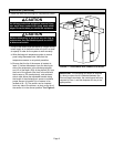
IMPORTANT: The temperature sensor is required.
If a short or open circuit is detected between the
Discharge Air Sensor (DAS) terminals, the control
panel will only respond to Zone 1 and the dampers
will not close.
1
The G terminal will remain energized for 1 minute.