


Page 4
If a return air plenum is used, the return air grille should be
immediately in front of the opening in the plenum to allow
for the free flow of return air. When not installed in front of
the opening, there must be adequate clearance around the
air handler to allow for the free flow of return air.
Installation
Each unit consists of a blower assembly, refrigerant coil,
and controls, in an insulated galvanized steel factory
finished enclosure. Knockouts are provided for electrical
wiring entrance.
For ease in installation, it is best to make any necessary
coil configuration changes before setting air handler in
place.
REFRIGERANT METERING DEVICE
CB25UH units are equipped with a factory-installed check
expansion valve.
UPFLOW APPLICATION
1. The air handler must be supported on the bottom only
and set on solid floor or field‐supplied support frame.
Securely attach the air handler to the floor or support
frame.
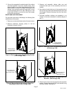
2. If installing a unit in an upflow application, remove the
horizontal drain pan. IMPORTANT - The horizontal drain pan
is not required in upflow air discharge installations; its removal
provides the best efficiency and air flow.
3. Place the unit in the desired location and slope unit as
previously mentioned. Connect return and supply air
plenums as required using sheet metal screws.
4. Install units that have no return air plenum on a stand
that is at least 14” from the floor. This will allow proper
air return.
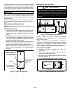
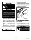
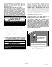
HORIZONTAL DRAIN PAN
IMPORTANT! REMOVE PAN
FOR BEST EFFICIENCY
AND AIR FLOW.
UPFLOW
DRAIN PAN
UPFLOW DRAIN CON
NECTIONS (BOTH
SIDES; USE ONE SIDE
OR OTHER)
HORIZONTAL DRAIN
CONNECTIONS
(BOTH SIDES; NOT
USED)
Figure 1. Upflow Configuration
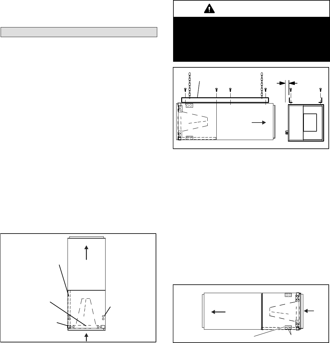
HORIZONTAL APPLICATIONS
IMPORTANT
When removing the coil, there is possible danger of
equipment damage and personal injury. Be careful when
removing the coil assembly from a unit installed in right-
or left-hand applications. The coil may tip into the drain
pan once it is clear of the cabinet. Support the coil when
removing it.
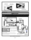
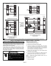
FRONT VIEW END VIEW
ANGLE IRON OR SHEET
METAL
ELECTRICAL INLET CLEAR
ANCE 4 IN. (102 MM)
MAXIMUM 1/2”
LONG SCREW
AIR FLOW
Figure 2. Suspending Horizontal Unit
NOTE — When the unit is installed in horizontal
applications, a secondary drain pan is recommended.
Refer to local codes.
NOTE — This unit may be installed in left-hand or
right-hand air discharge horizontal applications. Adequate
support must be provided to ensure cabinet integrity.
Ensure that there is adequate room to remove service and
access panels if installing in the horizontal position.
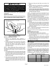
LEFT-HAND DISCHARGE
1. Determine knockouts required for drain line
connections.
2. With access door removed, knock out drain line
opening for installing drain lines.
3. Set unit so that it is sloped toward the drain pan end of
the unit (see figure 10).
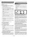
4. The horizontal configuration is shown in figure 3.
Drains
AIR FLOW
KNOCKOUT
LEFT‐HAND DRAINS
Figure 3. Left‐Hand Discharge Configuration