


Page 4
3 - Turn off all electrical power to the unit.
4 - This unit is equipped with an ignition device which auĆ
tomatically lights the burners. Do not try to light it by
hand.
5 - Remove the unit access panel.
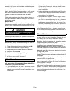
6 - Turn gas valve knob to OFF. See figure 3.
Figure 3
HONEYWELL VR8205 Series Gas Valve
Gas Valve Shown In OFF Position
manifold
pressure
tap
high fire adjusting screw
(under cap)
low fire
adjusting screw
(under cap)
inlet pressure tap
7 - Wait five (5) minutes to clear out any gas. If you then
smell gas, STOP! Immediately call your gas supplier
from a neighbor's phone. Follow the gas supplier's inĆ
structions. If you do not smell gas go to next step.
8 - Turn gas valve knob to ON. Do not force the knob.
9 - Replace the unit access panel.
10 - Turn on all electrical power to the unit.
11 - Set thermostat to desired setting.
NOTE - When the unit is first started, steps 1 through
11 may need to be repeated to purge air from pilot line.
12 - If the appliance still will not operate, follow the instrucĆ
tions Turning Off Gas to the Unit" and call your service
technician or gas supplier.
Turning Off Gas to the Unit
1 - Set thermostat to lowest setting.
2 - Turn off all the electrical power to unit if service is to be
performed.
3 - Remove the unit access panel.
4 - Turn gas valve knob to OFF. Do not force the knob.
5 - Replace the unit access panel.
Filters
A filter must be in place anytime the unit is operating. The
filter may be located in the unit or installed in a return air
grille. Ask your dealer to show you the filter location. The
filter should be inspected monthly and cleaned when necĆ
essary to assure proper that the furnace operates properly.
Filters used inside the GHR32 series units are available
from Lennox and must be ordered separately. These foam
filters may be cleaned for reuse. If the filters need to be reĆ
placed, order Lennox part #31J81 for 14 X 25 inch filters for
the GHR32Q-50, -75 and GHR32V-75. Number P-8-7831
is for 20 X 25 inch filters which are used with the GHR32Q,
and V-100 and the GHR32Q-120 units. See figure 4 for reĆ
moving the filter from the unit. Use the following procedure
to clean the filter.
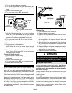
Figure 4
Press up on side filter clip to
release filter
(One on each side of cabinet)
FILTER
CABINET
FILTER
CLIP
BACK FILTER CLIP
FILTER
SIDE FILTER
CLIP DETAIL
CABINET
FILTER
CLIP
Cleaning Filter
1 - Turn off electric power to the unit.
2 - Remove blower access panel.
3 - Remove filter by pressing side filter clips and pulling
filter up and out.
4 - Clean filter with cold water and a mild soap. Direct waĆ
ter through filter in the opposite direction of air flow.
Remove all soap residue.
5 - Allow the filter to dry, then spray with Filter HandicoatĆ
er (P-8-5069) prior to reinstallation. This spray is availĆ
able from your Lennox dealer.
6 - Replace the filter in the blower compartment under the
rear filter clip. Press on filter sides. The filter clips flex,
allowing filter to snap into place.
7 - Replace the blower access panel.
WARNING
Blower door must be securely in place when blower
and burners are operating. Gas fumes, which could
contain carbon monoxide, can be drawn into living
space resulting in personal injury or death.
Seasonal Inspections
A qualified service technician should inspect the complete
system each season (heating and cooling). The following
maintenance procedures should be conducted by a
qualified service technician. Do not attempt to service
the unit in any way.
During a seasonal check the service technician will inspect
the indoor blower and the burner flames along with the
venting system.
Venting System
Annually (before heating season) inspect furnace venting
system, heat exchanger, and burners for corrosion, deteriĆ
oration, or deposits of debris. Remove any obstructions.
Inspect furnace venting system to make sure it is in place,
physically sound, and without holes or blockage. Vent conĆ
nector must be in correct position, sloped upward and be
physically sound without holes.