Page 3
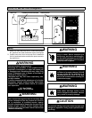
B−To Turn Off Gas To Unit
1− If using electroĆmechanical thermostat, set to the lowĆ
est setting.
2− Turn off all electrical power to unit if service is to be
performed.
3− Remove heat section access panel.
4− Turn knob on Honeywell gas valve clockwise until
it stops. Depress knob and turn clockwise to OFF.
Turn knob on White Rodgers 180° either way to off.
Do not force.
5− Replace heat section access panel.
WARNING
Danger of explosion. Can cause injury
or death. Do not attempt to light
manually. Unit has a direct spark
ignition system.
Flue Passage and Vent Inspection
Annually, before heating season, inspect combustion air
louvers, vent cap, heat exchanger, burners and combusĆ
tion air inducer for corrosion, deterioration or deposits of
debris. Remove any obstructions or blockage.
Burner Flame
WARNING
Danger of explosion and fire. Can cause
injury or product or property damage.
Periodically inspect burner flame to enĆ
sure proper unit operation.
The primary air is permanently set for normal operation.
The flame will be basically blue with some clear yellow
streaking in the end of the flame. Inspect burner flame peĆ
riodically during heating season using inspection port
provided on the burner access panel.
Service
To maintain efficiency and longevity, your equipment
must be serviced yearly by a qualified service technician.
Failure to provide proof of proper service can void the
warranty.
A−Servicing Filter
Filters must be installed in the return air system. Filters
should be checked monthly and replaced when necesĆ
sary. Take note of air flow direction marking on filter frame
when reinstalling filters.
NOTE−Filters must be U.L.C. approved or equivalent for
use in Canada.
B−Lubrication
All motors are lubricated at the factory. No further lubricaĆ
tion is required.
Service Reminder
Call a qualified service technician if the unit is inoperaĆ
tive. Before calling, always check the following to be
sure service is required:
1− Be sure electrical disconnect switches are ON.
2− Check room thermostat for proper setting.
3− Replace any blown fuses or reset circuit breakers.
4− Gas valve should be ON.
5− Air filters should not be plugged, limiting air flow.
6− Make sure all access panels are in place.
Repair Parts Listing
The following repair parts are available. When ordering parts, include the complete model number and serial number
listed on the unit rating plate − e.g. GCS20−024−50−1P
HEATING PARTS
Heat Exchanger
Combustion Air Inducer Assembly
Burner Sub−Assembly
Combustion Air Orifice
Gas Orifices
Ignition Electrode Assembly
Flame Sensor
Burner Gasket
Gas Valve
Limit Control
Flue Cap
Vent Cap Gasket
Secondary Limit
Roll−Out Switch
Combustion Air Inducer Gaskets
COOLING PARTS
Compressor
Compressor Run Capacitor
Expansion Valve
Condenser Fan Motor
Condenser Fan Blade
Condenser Fan Run Capacitor
Condenser Fan Motor Mounting Bracket
Fan Grille
Grille Retaining Nut
Indoor Blower Motor
Blower Motor Run Capacitor
Blower Wheel
Strainer
Distributor
Time Delay
ELECTRICAL PARTS
Compressor Contactor (K1)
Blower Relay (K3)
Blower Limit Relay (K20)
Combustion Air Inducer
Relay (K13)
Control Transformer
Ignition Control
Blower Delay Relay (K25 )


