


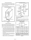

Usesheetmetalshearstoremovethecutoutfromtheside
ofthecabinet.Usethetwoprovidedsheetmetalscrewsto
installthecutoutonthetopcaptocovertheoriginalflue
outletopening.Seefigure15.
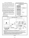
TheG50UH(X)seriesunitsareclassifiedasfan-assisted
CategoryIfurnaceswhenverticallyventedaccordingto
thelatesteditionof NationalFuelGasCode(NFPA54/
ANSI Z223.1 ) in the USA and the current standards of CSA
B149 Natural Gas and Propane Installation Codes in Can-
ada. A fan-assisted Category I furnace is an appliance
equipped with an integral mechanical means to either draw
or force combustion products through the combustion
chamber and/or heat exchanger.
NOTE - Use these instructions as a guide. They do not su-
persede local codes. This furnace must be vented accord-
ing to all local codes these installation instructions, and the
provided venting tables in these instructions
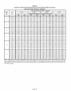
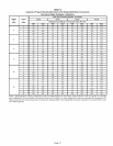
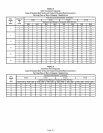
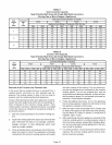
The venting tables in this manual were extracted from the
National Fuel Gas Code (NFPA 54 / ANSI Z223.1 ) and are
provided as a guide for proper vent installation. Proper ap-
plication, termination, construction and location of vents
must conform to local codes having jurisdiction. In the ab-
sence d local codes, the NFGC serves as the defining doc-
ument.
Refer to the tables and the venting information contained in
these instructions to properly size and install the venting
system.
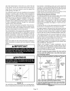
klMPORTANT
kWARNING
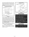
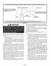
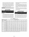
VENT CONNECTION
VENT
PIPE
FURNACE
FLUE TRANSITIOF
COLLAR
FIGURE 16
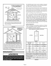
Use self-drilling sheet metal screws or a mechanical fas-
tener to firmly secure the vent pipe to the round collar of the
flue transition. If self-drilling screws are used to attach the
vent pipe, it is recommended that three be used. Drive one
self-drilling screw through the front and one through each
side of the vent pipe and collar. See figure 16.
Install the first vent connector elbow at a minimum of six
inches (152 mm) from the furnace vent outlet.
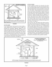
Venting Using a Masonry Chimney
The following additional requirements apply when a lined
masonry chimney is used to vent this furnace.
Masonry chimneys used to vent Category I central fur-
naces must be either tile-lined or lined with a listed metal
lining system or dedicated gas vent. Unlined masonry
chimneys are prohibited. See figures 17 and 18 for com-
mon venting.
A chimney with one or more sides exposed to the outside of
the structure is considered to be an exterior chimney.
An exterior masonry chimney that is not tile-lined must be
lined with B1 vent or a listed insulated flexible metal vent.
An exterior tileqined chimney that is sealed and capped
may be lined with a listed uninsulated flexible metal vent.
If the existing chimney will not accommodate a B1 vent or
an insulated flexible vent pipe liner, either the chimney
must be rebuilt to accommodate one of these liners or an
alternate approved venting method must be found.
Insulation for the flexible vent pipe must be an encapsu-
lated fiberglass sleeve recommended by the flexible vent
pipe manufacturer. See figure 17.
G50UH units installed in upflow applications may be
vented into a tile-lined masonry chimney without using a
listed metal liner, provided that the optional masonry chim-
ney vent adapter kit (18M79) is used. Instructions provided
with the kit must be followed exactly.
DO NOT insulate the space between the liner and the
chimney wall with puffed mica or any other loose gran-
ular insulating material
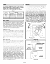
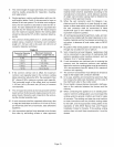
CommonVenting Using Metal-Lined Masonry Chimney
T MAX. LENGTH
-- SEE NOTE 1
BELOW.
VE%OO.o%OTOR "
SEALED
/
II
II EXTERIOR
CHIMNEY WITH
II METAL
II LINER
'1
__ .,J
PERMANENTLY
SEALED FIREPLACE
OPENING
NOTE 1 - Refer to the provided venting tables for installations in the USA
and the venting tables in CSA B149 for installations Canada.
NOTE 2 - Either single-walled or double-walled vent connector may be
used. Refer to the capacity requirements shown in the provided venting
tables for installations in USA and the venting tames in current CSA
B149 for installations in Canada.
FIGURE 17
Page 13