


CHIMNEY
OR GAS
VENT_
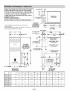
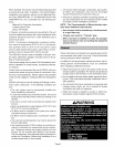
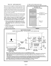
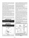
EQUIPMENT IN CONFINED SPACE
ALL AIR FROM OUTSIDE
(All Air Through Ventilated Attic)
VENTILATION LOUVERS
(Each end of attic)
FURNACE
INLET AIR
(Ends 12 in.
above bottom)
HEATER
NO TE- The inlet and outlet air openings shall each have a
free area of at least one square inch (645 mm 2)per 4,000
Btu (1.17 kW) per hour of the total input rating of all equip-
ment in the enclosure.
FIGURE 4
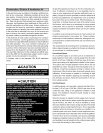
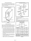
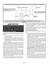
A _ EQUIPMENT IN
TT'_. JJ_ CONFINED SPACE
I I "_'Y _ ALLAIRFROM
I 1
OUTLET AIR
FURNACE
I1"- ,,
I ii I I I I I I I I I I I
NOTE - Each air duct opening shall have a free area of at least
o 2
ne square inch (645 mm J per 2, 000 Btu (.59 kW) per hour of
the total input rating of all equipment in the enclosure. If the
equipment room is located against an outside wall and the air
openings communicate directly with the outdoors, each open-
ing shall have a free area of at least one square inch (645 mm 2)
per4,000 Btu (1.17 kW) per hour of the total input rating of all
other equipment in the enclosure.
FIGURE 5
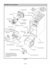
-&WARNING
The G50UH(X) gas furnace can be installed as shipped
in either the upfiow position or the horizontal position,
with right-hand or left-hand air discharge.
Select a location that allows for the required clearances
that are listed on the unit nameplate. Also consider gas
supply connections, electrical supply, vent connection,
and installation and service clearances [24 inches (610
mm) at unit front]. The unit must be level.
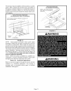
NOTE - 1/3 hp blower motors are equipped with four flex-
ible mounting legs. 1/2 hp blower motors are equipped with
three flexible legs and one rigid leg. The rigid leg is
equipped with a shipping bolt and a flat white plastic wash-
er (rather than the rubber mounting grommet used with a
flexible mounting leg). The bolt and washer must be re-
moved before the furnace is placed into operation. Af-
ter the bolt and washer have been removed, the rigid leg
will not touch the blower housing.
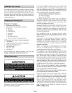
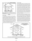
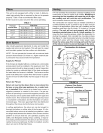
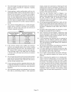
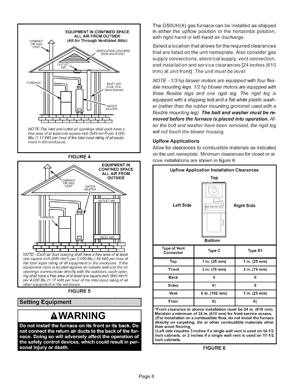
Upflow Applications
Allow for clearances to combustible materials as indicated
on the unit nameplate. Minimum clearances for closet or al-
cove installations are shown in figure 6.
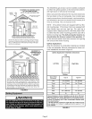
Upflow Application Installation Clearances
Top
Left Side
Right Side
Type of Vent
Connector
Top
*Front
Back
Sides
Vent
Floor
Bottom
Type C
1 in, (25 ram)
3 in, (76 ram)
0
Ot
6 in. (152 ram)
05
Type B1
1 in, (25 ram)
3 in, (76 ram)
0
0
1 in. (25 ram)
0J;
*Front clearance in alcove installation must be 24 in. (610 ram).
Maintain a minimum of 24 in. (610 ram) for front service access.
SFor installation on a combustible floor, do not install the furnace
directly on carpeting, tile or other combustible materials other
than wood flooring.
l-Left side requires 3 inches ifa single wall vent is used on 14-1/2
inch cabinets, or 2 inches if a single wall vent is used on 17-1/2
inch cabinets.
FIGURE 6
Page 8