


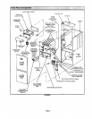
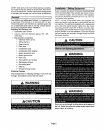
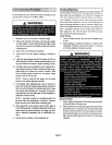
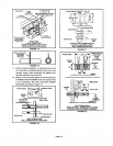
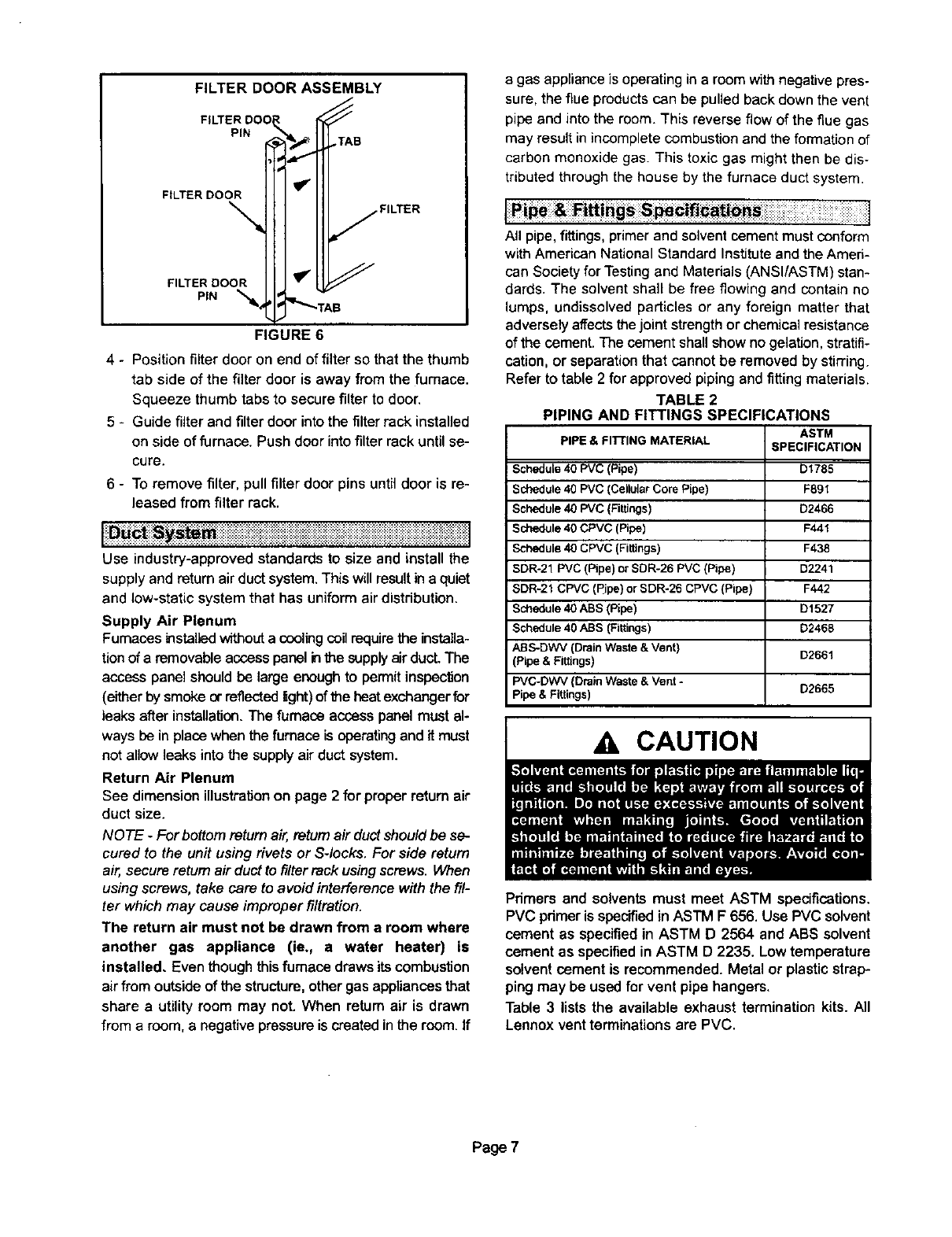
FILTER DOOR ASSEMBLY
FILTER DO0_ _
PIN _T_ TAB
FILTER DOOR I I I _'l]l
FILTER
FIGURE 6
4 - Positionfilter door on end offilter so that the thumb
tab side of the filter door is away from the furnace.
Squeeze thumb tabs to secure filter to door.
5 - Guide filter and filter door into the filter rack installed
on side of furnace. Push door into filter rack until se-
cure.
6 - To remove filter,pull filterdoor pins untildoor isre-
leased from filter rack,
Use industry-approved standards to size and install the
supply and return air duct system. This will result in a quiet
and low-static system that has uniform air distribution.
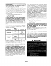
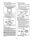
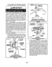
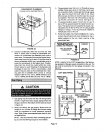
Supply Air Plenum
Furnaces installedwithout a cooling coilrequirethe installa-
tion of a removable access panel inthe supplyair ducL The
access panel should be large enough to permit inspection
(either by smoke or reflected light)of the heat exchanger for
leaks after installation. The furnace access panel must al-
ways be in placewhen the furnace isoperatingand it must
not allow leaks into the supply air duct system.
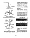
Return Air Plenum
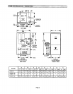
See dimensionillustrationon page 2 for proper returnair
duct size.
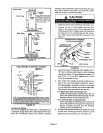
NOTE - For bottomreturn air, returnair ductshouldbe se-
cured to the unitusingrivets or Sqocks. For side return
air, secure return airduct to filterrack usingscrews. When
using screws, take care to avoid interference with the fil-
ter which may cause improper filtration.
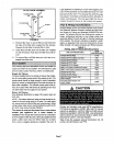
The return air must not be drawn from a room where
another gas appliance (ie,, a water heater) is
installed. Even thoughthisfurnace draws its combustion
air from outside of the structure, other gas appliances that
share a utility room may not. When retum air is drawn
from a room, a negative pressure is created in the room. If
a gas appliance is operating in a room with negative pres-
sure, the flueproducts can be pulled back down the vent
pipe and into the room. This reverse flow of the flue gas
may result in incomplete combustion and the formation of
carbon monoxide gas. This toxic gas might then be dis-
tributed through the house by the furnace duct system.
Pipe & _tttings S _¢ifi_ti_
J :::%:::::::::::::::: ::: : ::
]
All pipe,fittings,primerand solventcementmustconform
withAmericanNationalStandard Instituteand the Ameri-
can Society for Testingand Materials (ANSI/ASTM) stan-
dards. The solvent shall be free flowing and contain no
lumps, undissolved particles or any foreign matter that
adversely affects thejoint strength or chemical resistance
of the cement. The cement shall show no gelation, stratifi-
cation, or separation that cannot be removed by stining.
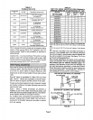
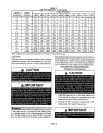
Refer to table 2 for approved piping and fitting materials.
TABLE 2
PIPING AND FITTINGS SPECIFICATIONS
ASTM
PIPE & FITrlNG MATERIAL SPECIFICATION
Schedule 40 PVC (Pipe) D1785
Schedule 40 PVC (CellularCore Pipe) F89t
Schedule 40 PVC (Fittings) D2466
Schedule40 CPVC (Pipe) F441
Schedule 40 CPVC (Fittings) F438
SDR-21 PVC (Pipe) or SDR-26 PVC (Pipe) D2241
SDR-21 CPVC (Pipe) or SDR-26 CPVC (Pipe) F442
Schedule 40 ABS (Pipe) D1527
Schedule 40 ABS (Fittings) D2468
ABS-DWV (Drain Waste& Vent)
(Pipe & Fittings) D2661
PVC-DWV (Drain Waste & Vent - D2665
Pipe & Fittings)
A CAUTION
Primers and solvents must meet ASTM specifications,
PVC pdrnerisspecifiedin ASTM F 656. Use PVC solvent
cement as specified in ASTM D 2564 and ABS solvent
cement as specified in ASTM D 2235. Low temperature
solvent cement is recommended. Metal or plastic strap-
ping may be used for vent pipe hangers.
Table 3 liststhe available exhaust termination kits. All
Lennox vent terminations are PVC.
Page 7