


Page 4
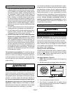
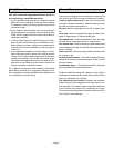
6 - White Rodgers 36E Gas Valve - Turn knob on gas
valve 180° either way to OFF. See figure 1.
7 - Wait five minutes to clear out any gas. If you then smell
gas, STOP! Immediately call your gas supplier from a
neighbor's phone. Follow the gas supplier's instructions.
If you do not smell gas go to next step.
WHITE RODGERS 36E SERIES GAS VALVE
GAS VALVE SHOWN IN OFF POSITION
p
M
C
HI
FIGURE 2
8 - White Rodgers 36E Gas Valve - Turn knob on gas
valve 180° either way to ON.
9 - Replace the access panel.
10 - Turn on all electrical power to to the unit.
11 - Set the thermostat to desired setting.
NOTE – When unit is initially started, steps 1 through 11
may need to be repeated to purge air from gas line.
12 - If the appliance will not operate, follow the instrucĆ
tions Turning Off Gas to Unit" and call your service
technician or gas supplier.
Turning Off Gas to Unit
1 - Set the thermostat to the lowest setting.
2 - Turn off all electrical power to the unit if service is to
be performed.
3 - Remove the access panel.
4 - White Rodgers 36E Gas Valve - Turn knob on gas
valve 180° either way to ON.
5 - Replace access panel.
Two–Stage Operation
The G27M is a two-stage gas-fired furnace, which can be
controlled by either a two-stage or single-stage room
thermostat.
The two-stage thermostat monitors the room temperature
and sends a signal to the G27M furnace when the temperĆ
ature falls below the desired setpoint. The furnace is then
turned on at low fire (first stage). If the room temperatures
continues to fall, the thermostat sends a signal to turn on
the unit at high fire (second stage).
When a single-stage thermostat is being used to control
the operation of the G27M furnace, the unit can either opĆ
erate on high fire (second stage) at all times or the unit can
be made to start on low fire (first stage) and automatically
switch to high fire (second stage) after a time delay, if the
demand is not satisfied on low fire (first stage).
NOTE – For more details on available options and for unit
adjustment, contact the Lennox Technical Support De-
partment.
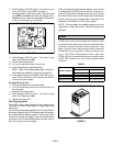
Filters
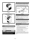
G27M series units are equipped with external filters
which should be inspected monthly and replaced when
necessary to assure proper furnace operation. See
table 1 for filter sizes. Replacement filters used with
G27M-60/75 units must have a minimum velocity ratĆ
ing of 400 FPM. Replacement filters used with
G27M-100/120 units require a minimum velocity rating
of 625 FPM. Figures 3, 4, and 5 show possible filter
locations.
TABLE 1
FILTER SIZE
MODEL NUMBER
UPFLOW DOWNFLOW
1 FILTER 2 FILTERS
G27M-45/60/75 16 in. X 20 in. X 1 in. 16 in. X 20 in. X 1 in.
G27M-100/120/140 20 in. X 20 in. X 1 in. 16 in. X 20 in. X 1 in.
UPFLOW FURNACE BOTTOM RETURN AIR
FIGURE 3