


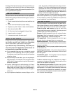
Filters
G20E and G20X series units are equipped with reusable
filters which should be inspected monthly and cleaned
when necessary to assure proper furnace operation. See
table 1 for filter sizes. Use the following procedure to
clean filter.
1- Turn off electric power to furnace.
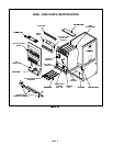
2- Remove blower access panel. Wait for blower to stop.
3- Remove filter by sliding up and out of filter brackets.
4- Wash filter with water and a mild detergent. For in-
creased efficiency, filter media should be sprayed
with filter Handicoater when dry.Filter Handicoater is
RP products no. 418 and is available as Lennox part
no. P-8-5069.
NOTE-If filter media must be replaced, order Lennox
part no. P-9-7831 for 20” x 25 ” filter, P-8-7822 for 16”
x 25” filter, 97H0601 for 18” x 25” filter, 97H0701 for
25” x25” filter, and 97H0801 for 24” x 30” filter.
5- Reinstall filter. Slide filter into top bracket and drop
into lower bracket.
NOTE-Do not replace reusable foam filters with
throw-away filters.
6- Replace blower access panel.
Q2-50, Q3-50, Q2-75,
Q3-75,
Q5/6-100, Q3/4-125,
Q5/6-125
16 X 25 X 1
20 X 25 X 1
16 X 25 X 1
20 X 25 X 1
Q4-75, Q3/4-100 16X25X1 18X25X1
Blower
Check and clean blower wheel for anydebris. Blower mo-
tor is prelubricated for extended bearin
g
life. No further lu-
brication is needed.
Pilot and Burner Flame
CAUTION
Check pilot flame and burner flame periodically to
ensure proper operation.
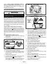
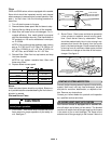
1-
Pilot Flame
-- Pilot flame must surround the end of
flame sensor for proper operation of pilot safety cir-
cuit. See fi
g
ure 7.
PILOT FLAME
(Side View)
BURNER
PILOT GAS
LINE
ELECTRODE
(G20E & G20X)
FIGURE 7
FLAME SENSOR
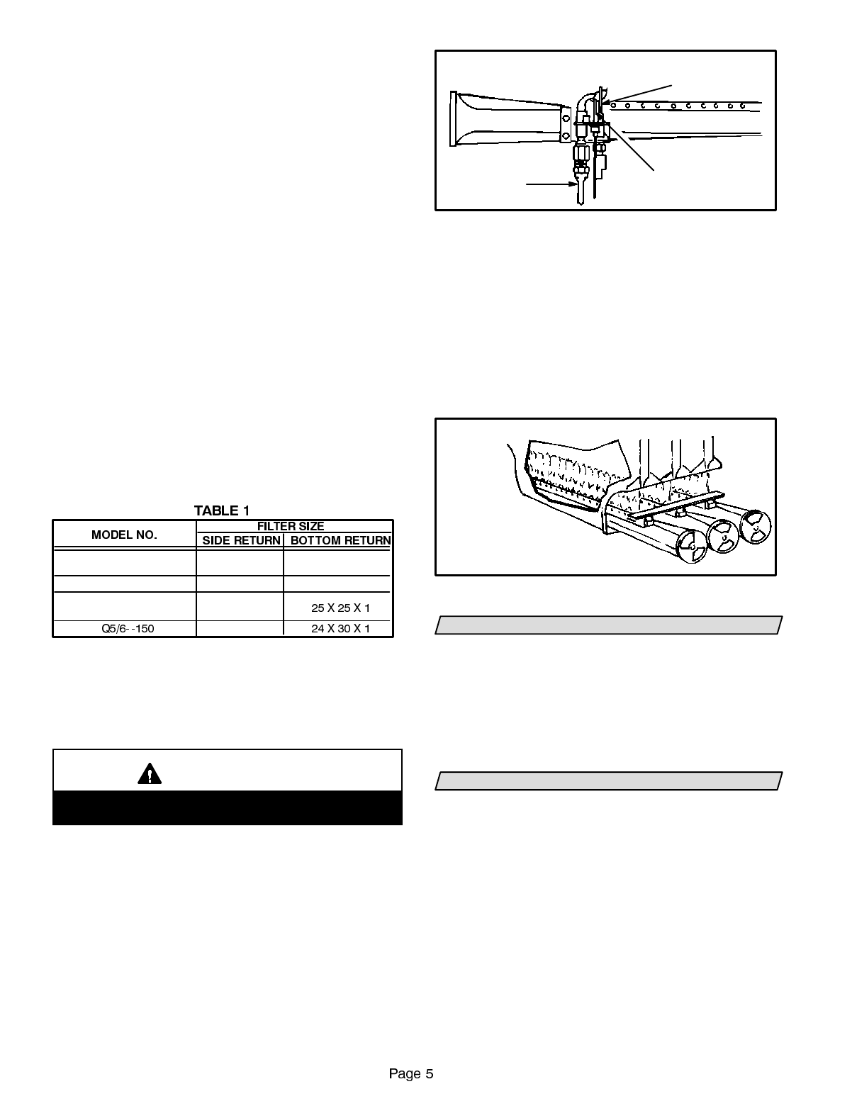
2-
Burner Flame
-- Start burner and allow to operate for
a few minutes to establish normal burnin
g
condi-
tions. Check burner flame by observation. Flame
should be predominantly blue in color, stron
g
in ap-
pearance and should rise directly from the burner
ports in the heat exchan
g
er. Check to see that flame
is burnin
g
from all continuous ribbon ports and that
flame does not impin
g
e on the sides of the heat ex-
chan
g
er. See fi
g
ure 8.
BURNER FLAME
FIGURE 8
NOTE-VIEW BURNER FLAME
THROUGH OBSERVATION PORT ON
BURNER BOX OR DAMPER OPENING
(Not Shown)
VENTING SYSTEM INSPECTION
Annually (before heatin
g
season) inspect furnace ventin
g
system, draft hood, vent cap, heat exchan
g
er, burners
and pilot for corrosion, deterioration, or deposits of de-
bris. Remove any obstructions.
Contact your Lennox dealer for a periodic unit inspection
by a qualified service technician.
BLOCKED VENT SHUT-OFF SYSTEM
Your Lennox furnace is equipped with a blocked vent
shut-off switch and a flame roll-out switch. The blocked
vent shut-off switch shuts off the
g
as supply to thefurnace
in the event of flue or vent blocka
g
e. The flame roll-out
switch shuts off the
g
as supply to the furnace if there is a