


icomfort Wi-Fit 7−Day Programmable Communicating Thermostat
Page 67
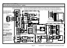
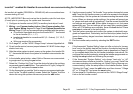
Setting up typical systemsĊFURNACE & HEAT PUMP (DUAL FUEL)
icomfortt−enabled Furnace & icomfortt−enabled HP unit (Dual fuel)
Dual fuel system using an icomfort−enabled gas furnace (G71MPP, EL296V,
SLP98, SL280) with an icomfort−enabled heat pump (XP17 or XP21 only).
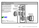
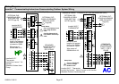
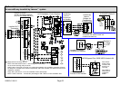
1. WiringĊsee Communicating System Wiring diagram on Page 59
and Optional Accessories Wiring (Page 61) for any accessories be-
ing installed with the system.
D 4−conductor thermostat wire from the icomfort Wi-Fit thermostat
to the gas furnace (R, i+, i−, C)
D 4−conductor thermostat wire from the furnace terminal strip to the
icomfort−enabled HP (R, i+, i−, C)
D Wiring as required for accessories
2. DO NOT cut any option link on furnace control.
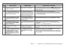
3. After the entire system is wired, power up the system; the icomfort Wi-
Fit thermostat will check the system for installed communication de-
vices.
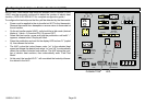
4. On the thermostat, go past the Add or remove non−communicating de-
vices" to the To adjust a setting" screen. Select System" from the de-
vice list using the up/down arrows and press the edit button
5. Select Balance Point Control and press edit. Use the down arrow to
select Enabled" and press save. High and Low Balance Points will ap-
pear in red.
6. Complete Balance Point Control by editing the High and Low Balance
Points. It is not necessary to change the defaults, but you must save
each setting. The red settings will go away after pressing save. Press
the back button to return to the adjust screen.
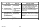
7. Use the arrows to select Furnace" from system devices list; press
edit. From this Furnace screen you will have access to the various air-
flow settings. Set the system air volumes according the needs of the
home. When you change certain settings, the system will prompt you
to please view and save all red settings". Use the arrows to select the
red settings and press edit. Either make changes or not, but press
save either way. The red settings will go away after pressing save.
When all CFM settings are complete, press the back button. Press
next step to advance to the tests button.
8. Test the system operation and confirm the HP unit is electrically ener-
gized and operational. Press done.
9. Exit the installer setup mode by selecting the EXIT button.
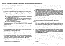
TIPS
S High & Low Balance points are enabled and adjusted under the install-
er section of the thermostat. In the equipment button select System"
and press edit. Scroll down to Balance Point Control" and press edit
and select Enabled and then save.
S An outdoor temperature sensor is provided in an icomfort−enabled heat
pump unit. To display the outdoor temperature on the home screen of
the thermostat, you must turn on (or off) the Outdoor Temp Display".
From the Home screen, press press for more area and select the
HELP icon. Press the user preferences box and scroll down to Out-
door Temp Display". Press the modify button and use the up/down ar-
rows to select On (or Off) and then press the save button. Press done
to return to the Home screen.
S Turn the Indoor Humidity Display on and off in a similar manner as
above.
S Gas heat is not provided to temper the air during defrost cycles.
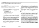
icomfortt−enabled Furnace &
non−communicating HP unit (Dual fuel)
NOTE − DO NOT use a conventional non−communicating heat pump unit in
an icomfort dual fuel system.
TIPS
S A conventional thermostat capable of controlling a dual fuel system,
like the ComfortSense
®
7000, must be selected for this type of applica-
tion.