


Page 5
L3011C THERMOSTAT
Thermostat RESET
Under some abnormal conditions, it may be desirable to
reset" the thermostat to its default condition. This can be
useful on rare occasions when the the thermostat is behav-
ing abnormally (e.g. after an electrical storm or power out-
age). The RESET button can be used to recover from this
situation.
The RESET button is an unlabeled, recessed button lo-
cated behind the door on the right−hand side of the thermo-
stat, just below the SETTINGS button. The RESET button
is visible in figure 3. Use a paper clip or small pencil to
press the RESET button. After the RESET button is
pressed, the thermostat settings will return to the defaults
listed in the Default Settings section.
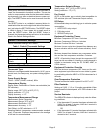
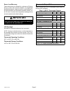
Default Thermostat Settings
Default thermostat settings are in table 1.
Table 1. Default Thermostat Settings
Mode Heat
Setpoint 70°F (or 21°C)
Fan Auto
Filter Reminder OFF (reminder setting = 0)
Equipment Protection
Timers
Reset back to zero
Technical Specifications
Thermostat Type
Electronic nonprogrammable thermostat for 1H/1C, gas or
electric heat, non−heat pump, non−power robbing applica-
tions.
Power Supply Range
18VAC − 30VAC (24VAC nominal), 60Hz
Temperature Display
Display Scale: Fahrenheit or Celsius user selectable (via
DIP switches)
Display range: 35°F (2°C) to 99°F (37°C)
Display resolution: 1°F (1°C)
Display Accuracy: +/−1°F
Temperature Measurement Range
Measurement Scale: Fahrenheit
Measurement Range: 35°F to 99°F
Measurement Resolution: 0.5°F
Measurement Accuracy: +/−1°F
Field Offset: via DIP switches to +/−3°F
Sampling Method: temperature measurements sampled
every 15 seconds. Displayed temperature is the average
of the last four measurements.
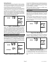
Temperature Setpoint Range
Setting range: 50°F (10°C) to 90°F (32°C)
Setting resolution: 1°F (1°C)
Fan Control
AUTO or ON modes, gas or electric heat compatible via
DIP switches (also see Thermostat Output section).
I/O Relays
All thermostat relays are latching type to minimize power
consumption.
1.. HEAT/COOL relay output
2.. FAN relay output
3.. SERVICE relay input
Equipment Protection Timers
Minimum Compressor OFF time: 5 minutes
Minimum Compressor ON time: 4 minutes
Minimum Furnace ON time: 3 minutes
Minimum furnace cycle time (elapsed time between any
furnace activation and the next furnace activation): 6 min-
utes.
Minimum elapsed time between any compressor activa-
tion and the next compressor activation: 6 minutes.
NOTE − All protection timers (except the compressor OFF
timer) can be over−ridden if a heating or cooling demand is
initiated or terminated using the UP, DOWN, HEAT, or
COOL buttons.
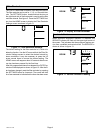
Equipment Protection Override
Both the minimum compressor OFF timer and the mini-
mum equipment cycle timer can be over−ridden by press-
ing and holding either the HEAT or COOL button down for 4
seconds.
Over−Temperature Protection
Thermal mechanical switch opens W1 at 93°F+/−6°F.
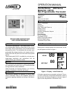
Filter Reminder
Settings of 0 (Off), 1, 3, 6 or 12 months are available. When
programmed time has elapsed, a FILTER indicator is dis-
played.
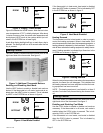
Service Reminder
The SERVICE indicator is displayed only under the follow-
ing conditions:
S if the thermostat Y1 terminal has been activated with
24VAC for at least 5 minutes, AND the L terminal is
shorted to the R terminal;
OR
S if the thermostat Y1 terminal has been activated with
24VAC for at least 5 minutes, AND the L terminal is
shorted to the C terminal.