


The defrost control is a solid state control
manufacturedby HamiltonStandard.The control
providesautomaticswitchingfrom normalheating
operationto defrost mode and back.The defrost
controlcontainsasolidstatetimerwhichswitchesan
externa] defrost relay through 1/4" male spades
mountedonthe control'scircuit board.Thecontrol
energizesthedefrostrelayat regular timed intervals.
On some units, a normally open defrost switch placed
in series between the defrost relay and the control
initiates defrost only when needed at the end of the
timed intervals. On other units, the control initiates
defrost on demand from the defrost thermostat,
7- Timing Jumper
A factory installed jumper on the circuit board
connects terminal Wl on the circuit board to one
of the three timing pins.
8- TST Pins
Each board is equipped with a test pins for use in
troubleshooting the unit. When jumpered
together, these pins reduce the control timing to
about 1/256 original time.
A CAUTION
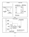
Defrost Control Components:
1- 24V Terminal
Terminat 24V receives 24VAC from the control
transformer. This terminal powers the control's
internal timer and relays. Terminal 24V must be
powered at all times to provide HOLD between
thermostat demands.
2 COM Terminal
Terminal COM provides 24VAC common.
3- HLD Terminal
Terminal HLD hold the internal timer in place
between thermostat demands and altows the unit
to continue timing upon resumption of
thermostat demand, tn most units, terminal HLD
is connected directly to thermostat demand.
4- OUT Terminal
Terminal OUT controls unit defrost when
connected to one side of the defrost relay coil. An
internal relay connected to terminal OUT closes
to allow external defrost relay to energize and
initiate defrost. At the end of the defrost period,
the internal relay connected to terminal OUT
opens to de-energize the external defrost relay.
5- RST Terminal
This terminal is not functional for the specified
application.
6- Timing Pins (T1,T2,T3)
Each of these pins provides a different timed
interval between defrosts (30, 60 or 90 seconds).
A jumper connects the pins to circuit board
terminal Wl. To change the interval between
defrosts, remove the jumper from the pin it is
connected to and reconnect the jumper to one of
the other available pins.
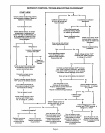
To Place Control in Test Mode:
1- Turn off all power to avoid damaging the circuit
board.
2- Make sure all control terminats are connected as
shown on unit wiring diagram before attempting
to place control in test mode.
IMPORTANT
3- Connect jumper to "TST" pins,
4- Turn indoor thermostat to heat mode and adjust
to highest temperature setting.
5- See table 1 for control timings in "TST" mode,
6- Turn on power to unit and re-adjust thermostat.
Be sure to remove jumper when test is complete.
TABLE 1
TEST MODE CONTROL TIMINGS
NORMAL !_ 30+3 60±6 : 90_9 _ 14+1,4
OPERATION MIN MIN i MIN. MIN.
"TST" PINS
1!7+0r7 14+1A i 21_+21 3-3_0.3
JUMPERED SEC. i SEC i SEC* i SEC
TOGETHER !
Page 3