


Page 6 # 48283B006
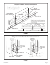
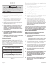
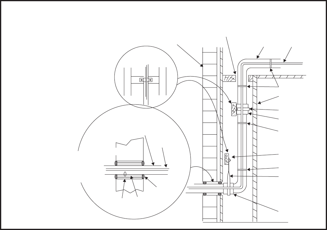
Figure 8
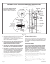
Refrigerant Line Sets: Installing Vertical Runs (new construction shown)
Outside Wall
Wood Block
Between Studs
IMPORTANT: Refrigerant
lines must not contact wall.
Vapor Line
Liquid Line
Wire Tie
Inside Wall
Strap
Sleeve
Wire Tie
Wire Tie
Strap
Wood Block
Sleeve
Vapor Line Wrapped
with Armaflex
Liquid Line
Caulk
PVC Pipe
Fiberglass
Insulation
Outside Wall
IMPORTANT:
Refrigerant
lines must not
contact structure.
NOTE: Similar installation practices
should be used if line set is to be
installed on exterior of outside wall.
3. Use silver alloy brazing rods (5% or 6% silver alloy for
copper-to-copper brazing or 45% silver alloy for
copper-to-brass or copper-to-steel brazing) which are
rated for use with HCFC-22 refrigerant.
4. Remove the Schrader core assemblies before brazing
to protect them from damage due to extreme heat.
Replace the cores when brazing is complete.
5. Wrap a wet cloth around the valve body and copper tube
stub to protect them from heat damage during brazing.
6. Braze the line set to the service valve. Quench the joints
with water or a wet cloth to prevent heat damage to the
valve core and opening port. The tube end must stay
bottomed in the fitting during final assembly to
ensure proper seating, sealing, and rigidity.
7. Install the factory-supplied fixed orifice (or thermal
expansion valve which is sold separately and which is
approved for use with HCFC-22 refrigerant) in the
liquid line at the indoor coil.
Refrigerant Metering Device
2SCU13 units are designed for use with either fixed orifice
or TXV systems. Refer to the appropriate following section
for information on installing the chosen refrigerant meter-
ing device.
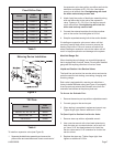
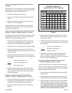
Fixed Orifice Systems
2SCU13 units are shipped with a fixed orifice refrigerant
metering device. Replace the existing indoor unit fixed
orifice with the orifice supplied with this unit. Place the
supplied fixed orifice sticker on the indoor cabinet after
installation. See Table 3 for the proper fixed orifice size for
each unit. In nonstandard applications, the provided fixed
orifice may not be appropriately sized.
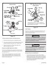
Install the fixed orifice as shown in Figure 9. Do not twist cap
tubes when loosening the seal nut from the orifice housing.
Use wrench to back up the distributor.
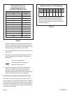
Expansion Valve Systems
Expansion valves equipped with Chatleff-type fittings are
available from the manufacturer. See Table 4 for proper
TXV for each unit.