


(2 each side) ,_
T
ADHESIVE-BACKED
FOAM TAPE
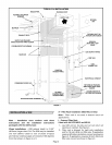
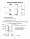
INSTALLATION OF SUPPLY AIR TRANSITION AND INTERNAL FILTER RACK
SUPPLY AIR TRANSITION (KIT CAT# 16L25)
SECURING SCREWS NOTE - FILTERRACK INSTALLATION REQUIRED
ONLY IF FILTERWILL BE INSTALLED INSIDE OF UNIT
"D" HOLES (Left side
installation holes)
"C" HOLES (Right side
installation holes
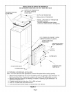
SUPPLY AIR TRANSITION
FILTER RACK TOP
CABINET SIDE
;MALL END OF TRANSITION
BLOWER DECK
\
;TALL LARGE END
OF TRANSITION TO
FRONT OF UNIT.
(If unit in installed one inch
further to the rear, rotate
transition 180 degrees.)
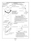
FILTER RACK TOP
VIEW A
,I,I,IB }3
1 inch
(25 mm)
INSTALL FILTER RACK TOP AS FOLLOWS:
(Right side installation shown)
1 - Loosen blower deck screws. Remove center two.
2 - Cut away any interfering insulation at A.
3 - Slide filter rack top between blower deck and cabinet and
push back to align "C" holes (right side installation holes).
(For left side installation flip bracket and use "D'holes.)
4 -Secure with existing screws.
5 - Fasten filter rack top with two additional self-drilling self
tapping screws at B approximately one inch from edge. See
view A.
6 - Re-tighten remaining blower deck screws.
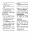
EXISTING BLOWER
DECK SCREWS
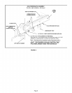
// CABINET SIDE
A
"_ FILTER RACK BOTTOM
J
1
VIEW A CABINETBASE
EXISTING BASE SCREWS
"FILTER RACK BOTTOM
"FILTER RACK DOOR
THUMB SCREW
INSTALL FILTER RACK BOTTOM AS FOLLOWS:
(Right side installation shown)
(Flip bracket for left side installation)
1 - Loosen base screws. Remove center two.
2 - Cut away any interfering insulation at A.
3 - Slide filter rack bottom between base and cabinet,
4 - Align center two holes and secure with existing screws.
5 - Re-tighten remaining base screws.
FIGURE 5
Page 7