


Page 13
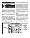
Unit Start−Up and Operation
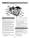
Each 15CHAX packaged cooling unit is factory−charged
with R−410A refrigerant. The compressor is hermetically
sealed, internally sprung and base−mounted with
rubber−insulated hold−down bolts.
Pre−Start Check List:
1 − Make sure refrigerant lines do not rub against the cabi-
net or each other.
2 − Inspect all electrical wiring, both factory− and field−
installed, for loose connections.
3 − Check voltage at the disconnect switch. Voltage must
be within the range listed on the unit nameplate. If not,
consult power company and have voltage condition
corrected before starting unit.
4 − Recheck voltage with unit running. If power is not with-
in the range listed on the unit nameplate, stop the unit
and consult the power company. Check unit amper-
age. Refer to unit nameplate for correct running amps.
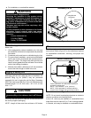
5 − Make sure filter is in place before unit start−up.
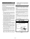
6 − Before placing the unit into full operation, energize the
unit for three false starts. Energize the compressor
just long enough for it to make a few revolutions, wait
five to seven minutes before repeating a second and
third time.
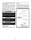
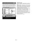
Cooling Sequence of Operation
When the thermostat calls for cooling, the R" to Y" circuit
is closed to energize the compressor contactor. The
contactor brings on both the compressor and outdoor fan.
The thermostat also closes the R" to G" circuit to energize
the circulating air blower. When the cooling demand is
satisfied, the thermostat opens the circuits, as well as the
compressor contactor. The compressor and outdoor fan
immediately stop. The circulating air blower continues
operating through a 90−second delay.
Unit compressors have internal protection. If there is an
abnormal rise in the compressor temperature, the
protector will open and the compressor will stop.
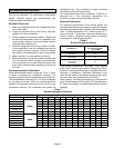
System Performance
For maximum performance of this cooling system, the
operating temperatures and pressure should be checked
and subcooling determined at Standard ARI test conditions
of 82_ F outdoor temperature / 80_ F indoor dry bulb / 67_ F
indoor wet bulb. If subcooling measured deviates from
values in table 6, refrigerant charge should be adjusted
accordingly for maximum performance.
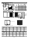
Table 6
Suction Superheat Values
Unit Model No.
Suction Superheat
82_F OD / 80_F IDDB
/ 67_F IDWB
15CHAX−24
15CHAX−30
12_
15CHAX−36 15_
15CHAX−42
15CHAX−48
15CHAX−60
10_
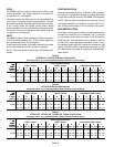
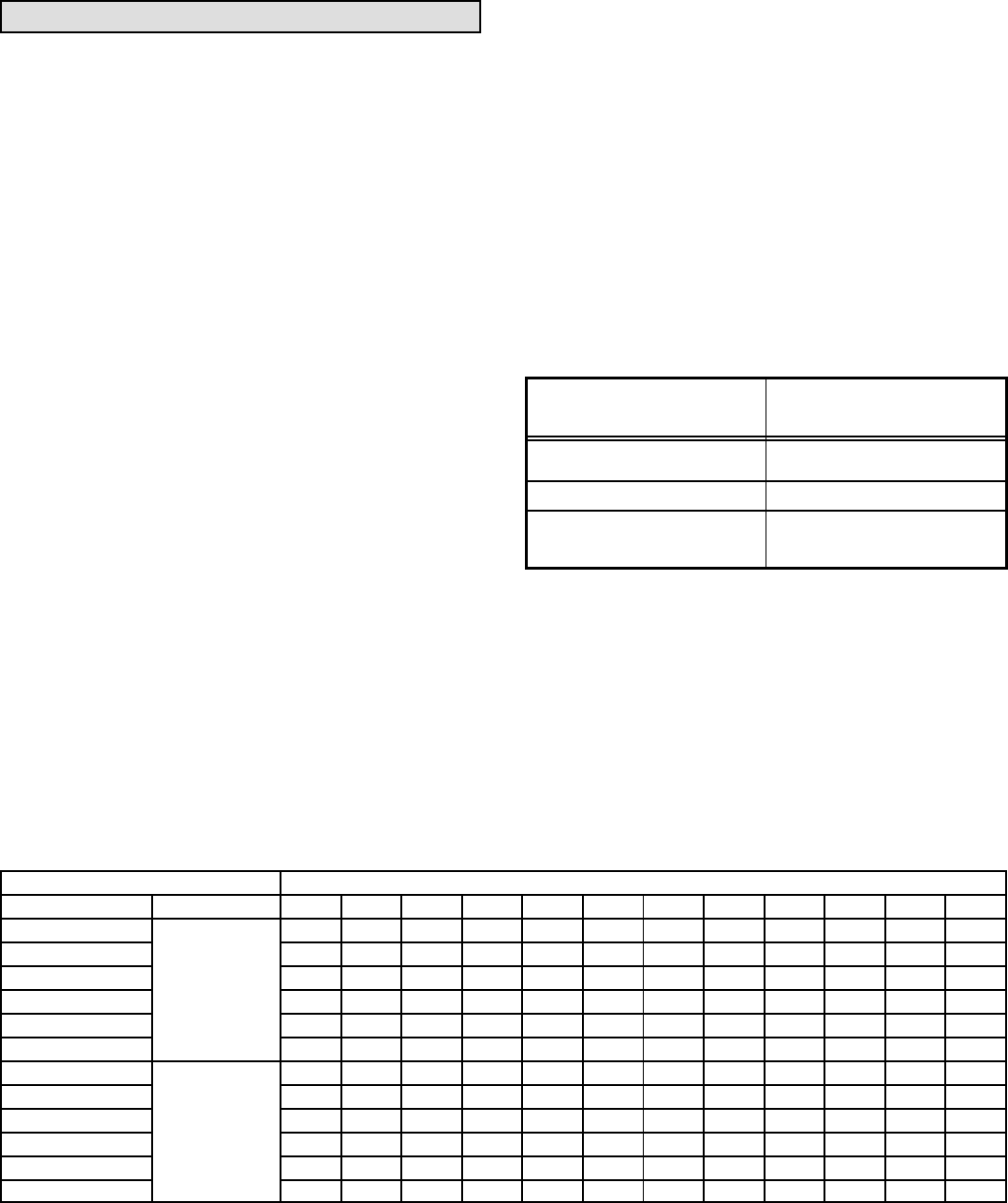
Verify system performance using table 7 as a general
guide. Table 7 should not be used for charging unit. Minor
variations in these pressures may be expected due to dif-
ferences in installations. Significant differences could
mean that the system is not properly charged or that a prob-
lem exists with some component in the system.
Used carefully, this table could serve as a useful service
guide. Data is based on 80°F dry bulb / 67°F wet bulb return
air. Allow unit operation to stabilize before taking pressure
readings.
Table 7
Normal Operating Pressures
80°F db / 67°F wb RETURN AIR Air Temperature Entering Outdoor Coil (°F)
UNIT PRESSURE 65 70 75 80 82 85 90 95 100 105 110 115
15CHAX−24 142 143 144 146 146 147 148 149 150 151 152 153
15CHAX−30 134 136 138 140 141 142 144 146 148 149 151 152
15CHAX−36
Suction
143 144 146 147 148 149 151 152 155 155 157 157
15CHAX−42
Suction
140 140 140 141 141 141 142 142 143 144 145 147
15CHAX−48 140 141 142 144 144 145 146 147 148 149 150 151
15CHAX−60 143 144 145 146 146 147 147 148 149 150 151 152
15CHAX−24 219 242 264 287 296 310 333 355 379 398 430 457
15CHAX−30 232 255 277 300 309 323 345 368 390 408 440 470
15CHAX−36
Liquid
244 268 292 316 326 340 363 369 410 429 461 493
15CHAX−42
Liquid
225 247 269 291 300 314 337 357 383 402 434 457
15CHAX−48 243 264 285 307 315 328 349 370 391 408 440 470
15CHAX−60 257 280 303 326 335 349 372 395 418 436 468 497