


21
NOTE: DIAGRAMS & ILLUSTRATIONS ARE NOT TO SCALE.
Maintenance Checklist:
The following should only be performed by a qualified service
technician.
CAUTION: Label all wires prior to disconnection when servic-
ing controls. Wiring errors can cause improper and dangerous
operation. Verify proper operation after servicing.
1. Annual inspection should be made and the following checks
performed:
oWhen unit is cool, open glass viewing door and inspect burner for
dirt, soot and lint accumulations and remove if necessary. If exces
-
sive soot accumulation is present on burner, have a qualified service
technician adjust burner for proper combustion.
oClean inside of glass viewing door with gas fireplace glass cleaner.
NEVER attempt to open door or clean glass when unit is hot.
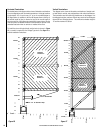
oCheck the hot air outlet vents for lint or other accumulations. Never
block or restrict vent openings or obstruct flow of ventilation air.
oCheck that direct vent pipe, air intake and flue are open and free of
soot, blockage, or debris.
oCheck gaskets once a year. Gaskets must be tight. Replace if neces-
sary.
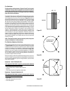
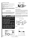
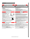
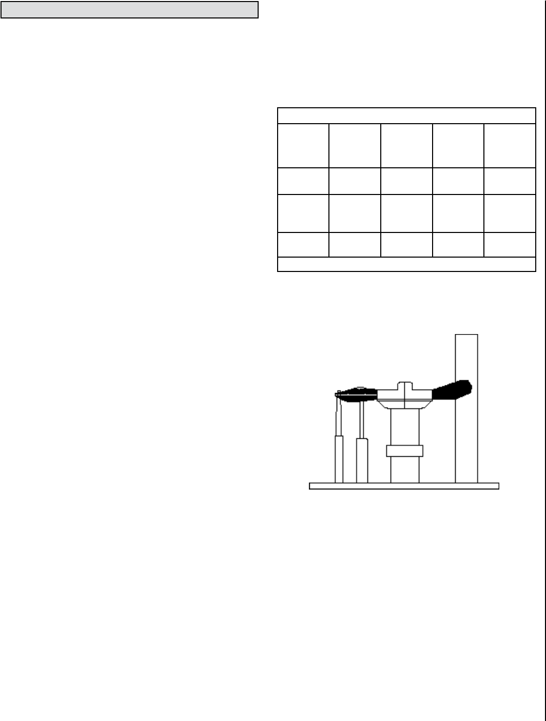
oInspect the pilot system for proper flame. NEVER ADJUST THE PILOT
until after the gas pressure has been checked and supply lines have
been completely bled (this may take an hour or more when bleeding
through the pilot). All pilots are checked and burned at the factory
prior to shipment. The pilot adjustment screw is located to the lower
left of the flame height control knob.
.25 Adjust the pilot screw to properly size the flames. The flames
should completely surround the thermopile and thermocouple and
extend across the main burner tube ports. Be careful not to back
the screw out of its threads.
oCheck that the area around the stove is kept clear and is free of
combustible materials, gasoline and other flammable vapors and
liquids.
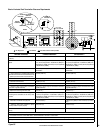
oCheck the millivolt system as per the table on this page.
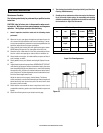
Proper Pilot Flame Appearance
Figure 35
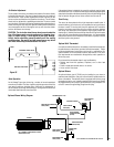
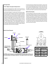
Millivolt and System Checks
Check
Test
To
Test
Connect
Meter
Leads to
Terminals
Thermostat
Connects
Meter
Reading
Should Be
A Complete
System
2 & 3 Closed
100 MV
or More
B Thermopile
Output
1 & 2
Open
Greater
Than
325 MV
C System
Resistance
2 & 3 Closed
2.5 Ohms
See Figure 34 - Wiring Terminals
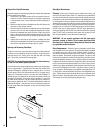
2. The viewing glass should be cleaned periodically (see Glass Door
Cleaning and Maintenance).
3. Should repairs or maintenance of the stove require the disassem-
bly of the vent/air intake system, the reassembly and resealing
should be completed by a qualified service technician and follow
the instructions on Page 10 of this manual.
MAINTENANCE AND SERVICING