


PLANNING YOUR INSTALLATION INSTALLATION
PAGE 7
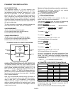
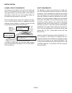
REDUCED MASONRY STRUCTURE CLEARANCE
(ALCOVE)
Your stove can be installed in a masonry structure with
reduced clearances if the structure was built to National
Building Code for fireplaces and chimneys (UBC 37).
The firebox of the masonry structure must be of ade-
quate size to allow a minimum of 6" (152 mm) clearance
to the sides and top of the stove and 2" (51 mm) clear-
ance to the rear. All stove models must be installed on
their original listed legs or base unless otherwise speci-
fied by OMNI Testing Laboratory.
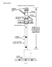
The minimum venting requirement is a listed chimney
liner that extends from the flue collar of the stove to the
first tile liner of the chimney where it is sealed. All joints
and connections must be made airtight to prevent leaking
and
downdrafts.
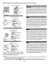
PROTECTED WALL CLEARANCE
Some local codes will allow reduced clearances when the
stove is installed adjacent to a protected wall system.
Your local building official must approve the variance.
Normally, the protected wall system is defined as a non-
combustible material with a minimum of 1" (25.4 mm) air
space behind. Check your local building codes or with a
qualified installer (Ref. NFPA 211).
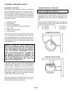
VENTILATION REQUIREMENTS
THE FRESH AIR REQUIREMENTS OF THIS APPLI-
ANCE MUST BE MET WITHIN THE SPACE WHERE IT
WILL BE INSTALLED.
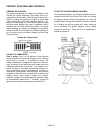
Ventilation is essential when using a solid fuel burning
heater. The combustion process of this heater uses oxy-
gen from inside the dwelling and it may be necessary to
open a window or install a vent to provide make-up air
into a dwelling that is well insulated (modern construction
standards have resulted in homes that are highly energy-
efficient and that allow little heat loss and air transfer).
Other appliances in the dwelling also contribute to re-
moving air from the dwelling (i.e. clothes dryers, exhaust
fans, fireplaces, and other fuel burning appliances). If the
available fresh air delivery in the dwelling is insufficient to
support the demands of these appliances, problems can
result (i.e. Excessive negative pressure can develop in
the dwelling which will affect the rate at which this appli-
ance can draft [See Draft Requirements, page 9], icing
can develop in some environments).
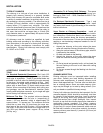
INSTALLING (OPTIONAL) MARBLE ACCENTS
See Optional Accessories, page 25 for ordering information.
Important Note; Optional marble cannot be used if tem-
perature probe is used.
Marble is a natural product and therefore each piece will
have its own unique character. Marble can be scratched
so care should be taken to avoid putting heavy or rough
objects (trivet/steamers) on the surface. If the marble
should become scratched, the scratch may be removed
or diminished by polishing it with jewelers rouge (which
can be purchased at many hardware stores). Do not in-
stall the marble before curing the paint.
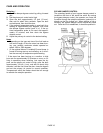
The marble set consists of 2 pieces. A large piece that
fits onto the stove top and a smaller piece that fits onto
the ashlip (located below the fuel door).
Installation Steps:
Install the ceramic fiber blanket, gasket strips and marble
set as follows:
Note: The fiber blanket and gasket strips are provided with the
stove: The marble sets are optional accessories.
1. Using scissors cut the ceramic fiber blanket so that it
fits into the recess of the stovetop.
2. Place the top marble piece onto the ceramic fiber
blanket.
3. Place the gasket strips into the recess of the ashlip
so that they are evenly spaced. This will slightly ele-
vate the marble so that it is not making direct surface
contact. Note: Insulation is not required in this area.
4. Place the ashlip marble onto gasket strips in ashlip
recess.