


2
NOTE: DIAGRAMS & ILLUSTRATIONS ARE NOT TO SCALE.
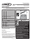
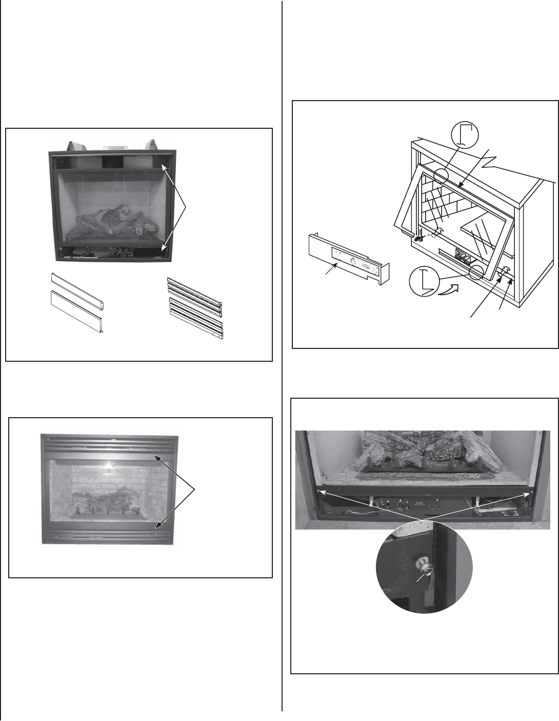
Figure 2 - Remove Top Panel
INSTALLATION INSTRUCTIONS:
1. Remove Top and Bottom Panels -
a. Remove the top louvered or radiant panel/hood assembly by pulling
the assembly up and out (see Figure 2). In instances where the radiant
panel is used and it is framed in with tile or other approved material, the
hood must still be removed by fi rmly pulling it forward until it releases
from the receiving brackets.
b. Remove the bottom louvered or radiant panel/hood assembly (refer to
Homeowner’s Care and Operation Manual).
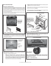
Remove Trim Panels
as shown. The trim
panels will be either
Louvered Panels or
Radiant Panels.
Louvered
Panels
Radiant
Panels
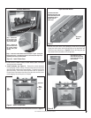
Figure 4 - GLASS DOOR ADJUSTMENT
Top Flange on Glass Door
Bottom Vee-fl ange Glass Door
Glass Door Latch
Glass Door
Firebox Floor
Some models will have a
modesty panel in the control
compartment (in front of
the valve). The appearance
will vary from the example
shown below.
Bustles
Figure 3 - Remove Bustles
Lift Bustles Up
And Off
Only Some Models
Have Bustles
Modesty Panel
2. Align Glass Door (see Figure 4) - Ensure the glass door assembly on
the fi replace is properly aligned as follows:
Note: Units with Modesty Panels - Remove the modesty panel,
if necessary, as follows: Lift the modesty panel by the tab on the
panel’s right end, pull the right end of the panel away from cabinet
and then pull the panel diagonally out of the corner post slots on
the left side of the unit. Remove the modesty panel carefully, so
that none of the wires become loose or disconnected.
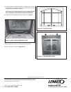
3. Install Firebox Bottom Cover Panel - For Models EDV-35/40/45, see
Figure 5a. For Model EDVST see Figure 5b.
Screw
Step 1 - Remove 2 fi re-
box bottom screws.
Step 2 - Install the Firebox Bottom Cover Panel (#5 in Figure 1) using the
existing screws that were removed. The top two holes on the panel align to
corresponding holes on fi replace.
Figure 5a - Install Firebox Cover
c. Remove Bustles - Some models have bustles (as shown in Figure 3)
which must be removed. If applicable, remove the top and bottom bustle
by lifting them up and out.
a. Open the latch(es) at the bottom of the glass door assembly as shown
in Figure 4 (refer to Homeowners Manual).
b. Adjust glass door so that it is evenly spaced and aligned to the fi replace
chassis on both sides. See Figure 4.
c. Fasten the latch(es). Ensure that the latch(es) are engaged with the
door’s vee-fl ange and fully closed. See Figure 4.
For EDV-35/40/45 Models