


10
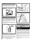
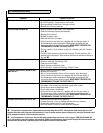
16.0 SPARK GAP
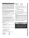
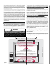
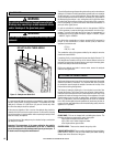
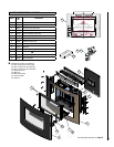
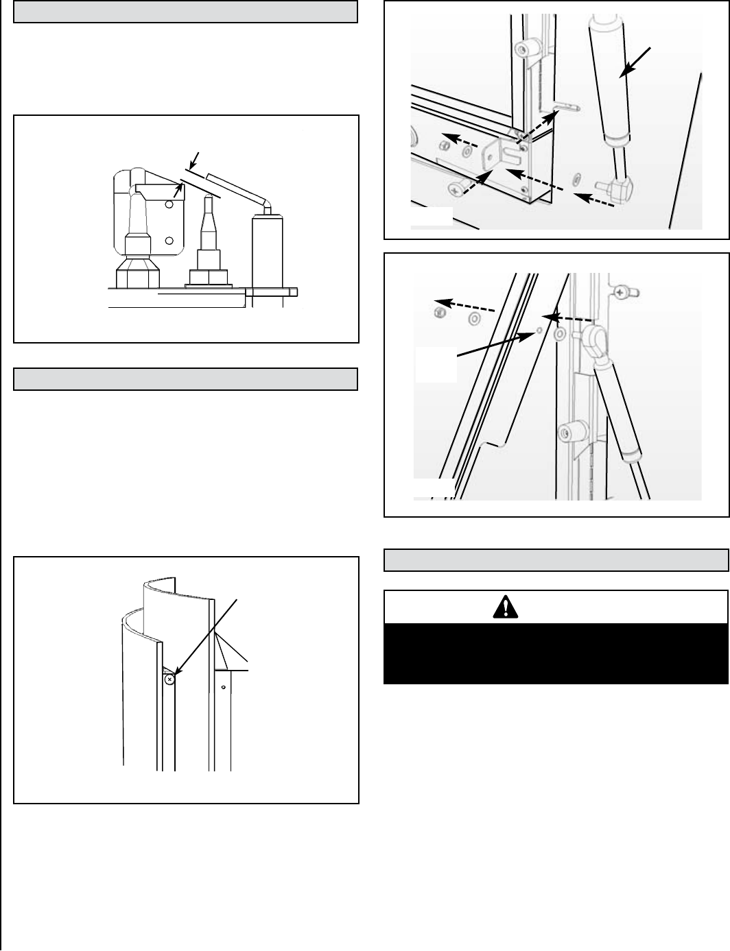
17.0 FITTING THE GLASS FACIA
The glass panel is supported by two self-locking M6 screws, one on
each side of the fireplace. The glass panel must be held in position
while the screws are inserted on each side - it is recommended to seek
assistance for this operation. See Figure 7a. The screws should be
screwed in fully and then undone one turn to allow the glass panel to
swing open for access to the controls.
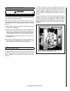
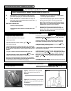
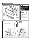
The appliance features a piston damper hinge assembly. The damper
assembly should be fitted onto the rear of the glass facia, on the lower
right hand side as follows:
Figure 7a - Glass Panel
18.0 BRIEFING THE CUSTOMER
WARNING
Do not add logs or ornaments such as pine cones,
vermiculite or rock wool. Using these added items
can cause sooting.
All instructions must be left in the possession of the user for safekeeping.
If at all possible, show the customer how to light and control the appliance
and show the customer how to remove and replace the glass facia.
After commissioning the appliance, the customer should be instructed
on the safe use of the appliance and the need for regular servicing. Fre-
quency of service depends on usage, but MUST be carried out at least
once annually. Advise that cleaning of the appliance may be achieved
when the appliance is cold using a damp cloth and mild detergent on
most surfaces.
Advise that the appliance will emit a "newness" smell for a time after
initial commissioning and that extra ventilation may be needed during
this time.
Advise to user to never place any objects on top of the appliance or
obstruction this area in any way.
A periodic visual check of the pilot flame and the burner flame should
be carried out.
1) Ensure that the piston portion of the damper is positioned as shown
in Figure 7b. Remove the Philips screw securing the frame, and fit the
lower piston bracket to the frame and fully re-tighten the screw.
Now fit the lower piston bolt through the hole in the bracket, with the
two nylon washers positioned either side of the bracket. Finally, attach
the “nyloc nut” to the damper thread, tighten and then release one
quarter turn. Check that the assembly can swivel.
The glass panel is
supported by two
self-locking M6
screws, one on
each side
Damper
Figure 7b
Fixing
hole
Figure 7c
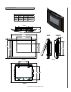
NOTE: DIAGRAMS & ILLUSTRATIONS ARE NOT TO SCALE
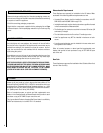
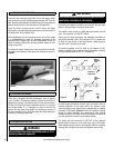
Figure 6 - Proper Spark Gap
1/8" to 3/16" Spark Gap
The gap between the spark electrode and the pilot should be 1/8” to
3/16” to produce a good spark. There should be no need to adjust this
(DO NOT ATTEMPT TO ADJUST THE GAP). If under any circumstances
the piezo electric spark fails, the pilot cannot be lit manually.
Adjustment to the
pilot is Not allowed