


11
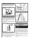
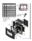
20.0 SERVICING THE BURNER
WARNING
Any change to this heater or its controls can be
dangerous.
First, remove the front glass facia as described in Section 17.0 only in
reverse, remove the valve cover (4 screws) and disconnect the gas con-
nection inside appliance. The gas connections to the gas valve can now
be released. Undo the four screws retaining the burner brackets to the
base and rear of the firebox. The burner may now be removed.
Remove the pilot and main burner pipes and blow through to dislodge
any debris. Now remove the in line restrictor and blow through to make
sure it is entirely clear.
Unclip the pilot lint gauze and clean with a soft brush. Clean the exterior of
the pilot assembly with a soft brush and blow through the flame ports on
the pilot head. Check the aeration holes are free from lint or dirt. The pilot
assembly can be removed if required by disconnecting the electrode HT
lead, gas pipe, thermocouple lead and unscrewing the mounting screws
and lifting away. The pilot assembly is a non-serviceable item and should
not be taken apart. Aeration holes must be clear internally for proper
operation. NEVER MODIFY OR BEND THE THERMOCOUPLE TO MAKE
THE PILOT STAY LIT. Modifications are dangerous and can have serious
unseen effects on safety. If the pilot will not stay lit there is a problem with
dirt, the gas supply to it, or the thermocouple needs replacement.
The gas valve is a non-serviceable item. If this needs replacement, remove
the cover plate then the securing screw holding the valve bracket in place,
remove all pipe unions, and the complete valve. Replacement must be
original manufacturers parts.
Re-assemble in the reverse of removal. Ensure setting pressures are as
stated in Table 1 on Page 3.
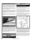
21.0 PILOT ASSEMBLY
WARNING
No adjustments are to be made to the ODS pilot
system. Tampering with this system can be extremely
hazardous.
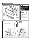
Remove the glass facia, glass panel and burner unit (as per servicing sec-
tion), lint arrestor and pilot assembly by using a screwdriver to remove
the retaining screws.
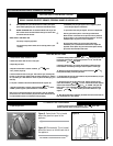
Clean the pilot assembly with a soft brush and blow through. Check the
aeration holes are free of any dirt or lint. Clean thoroughly internally,
the connection can be removed from the base of the pilot assembly
using two wrenches to make cleaning easier. Do not damage or try to
dismantle the pilot injector. The unit is factory set and the only check
necessary is to ensure the spark gap is correct. See Table 1 on Page
3 for gas setting.
NEVER MODIFY OR BEND THE THERMOCOUPLE TO MAKE THE PILOT
STAY LIT. If the pilot will not stay lit there is a problem with dirt, the
gas supply, or the thermocouple needs replacement. Modifications are
dangerous and can have a serious unseen effect on safety and therefore
MUST not be done. Replacements must be original manufacturers parts.
Re-assemble in the reverse of removal. Ensure setting pressures are as
stated in Table 1 on Page 3.
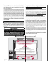
Turn off the fireplace at the gas supply. Ensure that the fireplace is fully
cold before attempting service. A suggested procedure for servicing
is detailed as follows;
1. Lay out the dustsheet and tools.
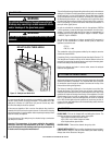
2. Remove the front glass facia as described in Section 17.0, only in
reverse.
3. Remove the glass door assembly (4 screws) and clean carefully.
Remove the valve cover plate (4 screws).
4. Inspect the burner and the catalysts and clean if necessary with a
soft brush.
5. Disconnect the gas supply. IMPORTANT NOTE: This must be done
by a licensed plumber or gas fitter and must conform to the require-
ments of the National Fuel Gas Code NFPA 54 / ANSI Z223.1 - latest
edition.
6. Undo the four screws retaining the burner support brackets.
7. Remove the burner unit, strip off the burner pipes and clean thor-
oughly.
8. Clean the in-line restrictor, pilot assembly and the burner tube. Do
not attempt to remove the pilot injector as this can cause damage.
9. Re-assemble components.
10. Re-connect the gas supply. Turn on the gas supply and perform a
gas leak test using gas leak test solution. Check pilot and burner for
good ignition.
11. Refit the valve cover and retaining screws.
12. Refit the glass door assembly.
13. Refit the facia as described in Section 17.0.
14. Check the purpose provided ventilation is unobstructed.
15. Light the appliance and test setting pressures.
16. Check safe operation of the appliance.
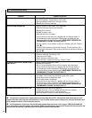
For specific servicing instructions, see relevant sections.
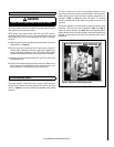
19.0 SERVICING
WARNING
Turn off the appliance and allow to cool before cleaning.
Verify proper operation after servicing.
WARNING
You must keep control areas, burners and circulating air
passageways of appliance clean. Failure to keep the
primary air opening(s) of the burner clear may result
in sooting and property damage. Inspect these areas of
appliance before each use. Have appliance inspected
yearly by a qualified service person. Appliance may
need more frequent cleaning due to excessive lint form
carpeting, bedding material, etc.