


2
NOTE: DIAGRAMS & ILLUSTRATIONS NOT TO SCALE.
Figure 6
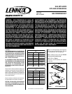
Step 8. Turn on gas supply and test for gas
leaks, using a soapy water solution.
Step 7. Attach appropriate conversion kit label
(
Figure 6
) to the rating plate on the appliance.
Printed in U.S.A. © 2006 by Lennox
P/N 750,217M REV. A 06/2007
Lennox Hearth Products reserves the right to make changes at any time, without notice, in design, materials, specifications, prices and also to discontinue colors, styles and products.
Consult your local distributor for fireplace code information.
NOTE: DIAGRAMS & ILLUSTRATIONS NOT TO SCALE.
LHP
1110 West Taft Avenue - Orange, CA 92865
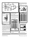
Figure 3
Figure 2
Figure 4
Note: If the ignitor is damaged, a replacement
kit is available, order Catalog Number 87L54.
Use pipe joint compound or Teflon tape on all
pipe fittings before installing (ensure propane
resistant compounds are used in propane ap-
plications, do not use pipe joint compounds
on flare fittings).
Pilot Stage
Terminal
Pressure-Tap
(Inlet)
Pilot Gas
Outlet
Supply Gas
Inlet
Pressure-Tap
(Manifold)
Burner Stage
Terminal
Ground
(TP)
PILOT
OUT
VENT
LO
TH
TP
TH
TP
HI
IN
IN
Gas Outlet
To Burner
Regulator
Mounting Screw
ELECTRONIC
Pilot
Hood
Sensor
Ignitor
Venturi
Air
Shutter
Rod
Valve
Lever Arm
Figure 5
Electronic Appliances
Step 4. Dexen Electronic Valves - See
Figure 2
and the instructions provided with the kit. Re-
move and discard the two pressure regulator
mounting screws. Remove the pressure regu-
lator and diaphragm. Discard all removed
components. Ensure the provided diaphragm
is installed properly onto the replacement pres-
sure regulator and install the new pressure
regulator using the new screws supplied with
the kit. Tighten screws.
See
Figure 3
and replace the pilot orifice as
follows: Remove pilot hood assembly to access
the phillipped pilot orifice. Remove and replace
the orifice with the one provided with the kit.
Exercise extreme care to prevent damage to or
breakage of the ignitor assembly.
Step 5. (Refer to
Figure 1
)
A. Remove the orifice from the manifold and
replace it with the one provided in the kit. See the
following table for orifice sizes for natural and
propane models
. Figure 4
illustrates the orifice.
B. Retrieve the burner and slide the venturi
tube over the orifice. Set the shutter adjusting
opening as shown in
Figure 5
.
Step 6. Reassemble the remaining compo-
nents by reversing the procedures outlined in
the preceding steps.
THIS APPLIANCE HAS BEEN CONVERTED TO:
NATURAL GAS
INPUT BTU/HR – 50,000
MANIFOLD PRESSURE – 3.5"
ORIFICE SIZE – (0.130)
THIS APPLIANCE HAS BEEN CONVERTED TO:
PROPANE/LPG
INPUT BTU/HR – 50,000
MANIFOLD PRESSURE – 10"
ORIFICE SIZE – (0.080)
.oNledoM
ezisecifirO
larutaNenaporP
53VDLE83#35#
04VDLE73#"260.0
54VDLE63#"560.0
03VDLPM"070.016#
53VDLPM65#74#
04VDLPM14#45#
54VDLPM04#35#
RENRUBNIAM
GNITTESGNINEPORETTUHSYROTCAF
sledoM
saGlarutaN
)mm(sehcni
saGenaporP
)mm(sehcni
53VDLE8/1)2.3(8/3)5.9(
04VDLE)6.1(61/1)5.9(8/3
54VDLE)2.3(8/1)5.9(8/3
03VDLPM)4.2(23/3)7.4(61/3
53VDLPM)4.2(23/3)6.1(8/1
04VDLPM)7.4(61/3)5.9(8/3
54VDLPM)7.4(61/3)7.21(2/1