


27
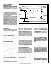
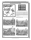
NOTE: DIAGRAMS & ILLUSTRATIONS ARE NOT TO SCALE.
LENNOX HEARTH PRODUCTS • MERIT
®
PLUS DIRECT VENT GAS FIREPLACES (MPD33/35/40/45) • INSTALLATION INSTRUCTIONS
B. Brush all joints and connections with the gas
leak test solution to check for leaks. If bubbles
are formed, or gas odor is detected, turn the
gas control knob (off/pilot/on) to the “OFF”
position. Either tighten or refasten the leaking
connection, then retest as described above.
C. When the gas lines are tested and leak free,
be sure to rinse off the leak testing solution.
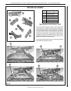
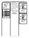
Step 8. VERIFYING APPLIANCE
OPERATION
With gas line installed, run initial system
checkout before closing up the front of the
unit. Follow the pilot lighting instructions
provided in the Care and Operation Instruc-
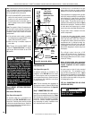
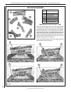
tions. For piezo igniter location on millivolt
appliances, see Figure 47 on Page 25.
Note: Lighting Instructions are also found on
the literature tag tied to the gas piping next
to the gas valve. To access the tag, open the
lower control compartment door (Figure 52)
by pushing in simultaneously the left and right
top corners of the door. (The door is hinged at
the bottom). Remove the bottom compartment
door by sliding the hinge pin, located at the
door’s left side, to the right until it disengages
from the left corner post hole.
When first lighting the appliance, it will take a
few minutes for the line to purge itself of air.
Once purging is complete, the pilot and burner
will light and operate as indicated in the instruc-
tion manual.
Turn on gas supply and test for gas leaks, us-
ing a gas leak test solution (also referred to as
bubble leak solution).
Note: Using a soapy water solution is an effec-
tive leak test solution but it is not recommended,
because the soap residue that is left on the
pipes/fittings can result in corrosion over time.
A. Light the appliance (refer to the lighting
instructions label in the control compartment
or in the Care and Operation Instructions
manual).
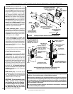
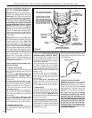
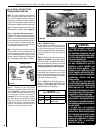
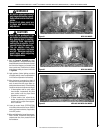
MILLIVOLT
Thermocouple
Hood Igniter Rod
3/8" Min
(9 mm)
Thermopile
Pilot
Nozzels
Subsequent lighting of the appliance will not
require such purging. Inspect the pilot flame
(remove logs, if necessary, handling carefully).
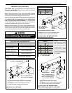
Millivolt Appliance Checkout
The pilot flame should be steady, not lifting
or floating. Flame should be blue in color with
traces of orange at the outer edge.
The top 3/8" (10 mm) at the pilot generator
(thermopile) and the top 1/8" minimum (tip)
of the quick drop out thermocouple should be
engulfed in the pilot flame.
The flame should project 1" (25 mm) beyond
the hood at all three ports (see Figure 53).
Replace logs if removed for pilot inspection.
To light the burner; turn “ON” the remote wall
switch and rotate the gas valve control knob
counterclockwise to the “ON” position (“ON”
will be at the top side of the valve).
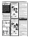
Electronic Appliance Checkout
To light the burner, turn ‘ON’ the unit-mounted
ON/OFF switch or the optional remote wall
switch. Ensure the igniter lights the pilot. The
pilot flame should engulf the flame rod as shown
in Figure 54.
Figure 53
Figure 52
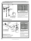
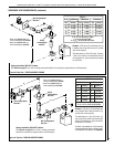
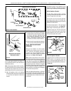
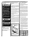
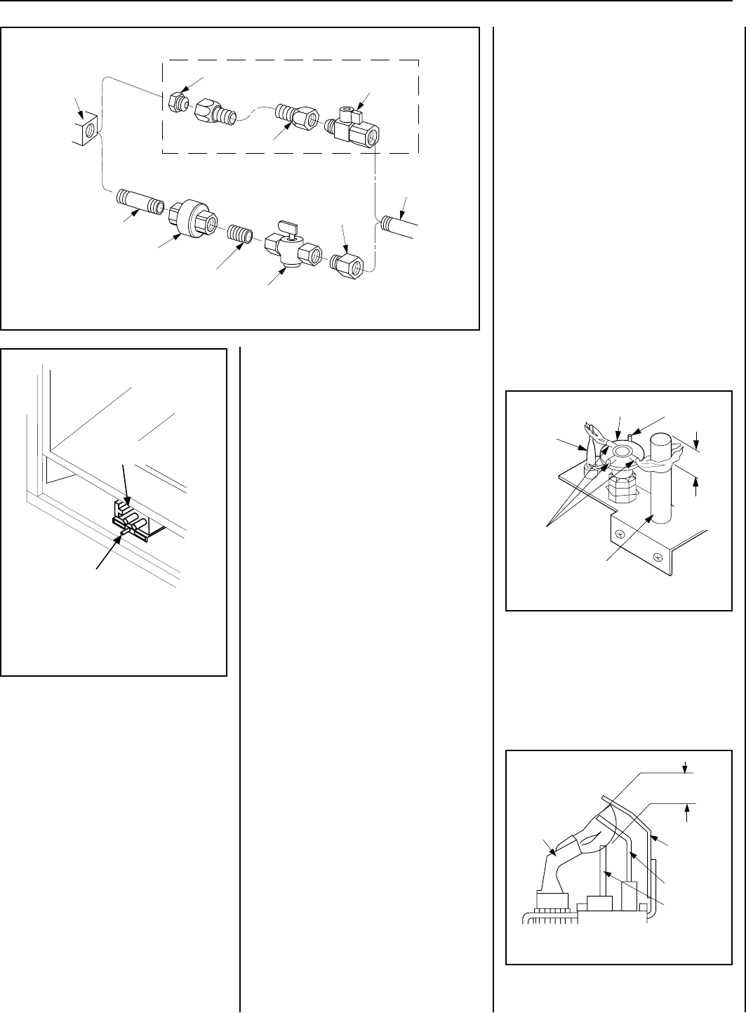
Figure 51: Gas Connection
Gas
Stub
1/2" x 3/8" Flare
Shut-Off Valve
3/8" Flex Tubing
3/8" NPT x 3/8"
Flare Fitting
3/8" Nipple
3/8" Union
3/8" Close Nipple
3/8" Shut-Off Valve
1/2" x 3/8"
Reducer
Gas
Valve
Optional Gas Flex Line Connector
ELECTRONIC
Proper Flame
Adjustment
Pilot
Nozzle
3/8 To 1/2 Inch
(9 mm to 13 mm)
Ground
Electrode
Flame Rod
Hot Surface
Igniter
Figure 54
Millivolt Gas Valve Showing
Piezo Ignitor Location
Piezo
Ignitor
SIT Gas Valve