


40
NOTE: DIAGRAMS & ILLUSTRATIONS ARE NOT TO SCALE.
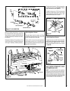
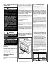
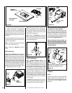
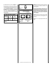
Air Shutter
Adjustment Lever
Venturi Tube
Arm
Pan Burner
Valve Access Side
of Fireplace
Firebox Subfloor
Figure 66
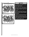
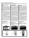
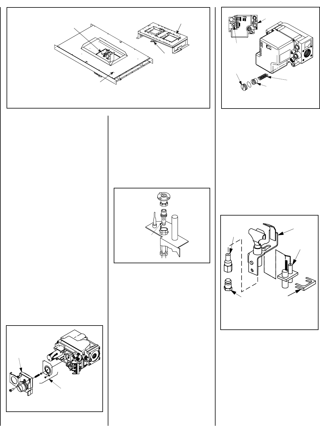
Pressure
Regulator
Remove
These
Components
P
S
I
OFF
I
ON
CONTROL
I
G
N
I
T
E
Gas Valve
Assembly
Manifold
Pressure
Test Port
Slotted
Cap
Spring
Adjusting
Screw
Figure 69
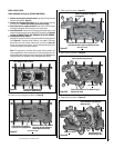
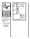
Figure 67
All Models
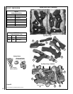
Step 8.
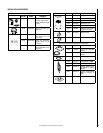
a. Remove the orifice from the manifold and
replace it with the one provided in the kit. The
following Table shows the orifice sizes for natu-
ral and propane models. Figure 71 illustrates
the orifice.
Pilot
Orifice
Pilot
Assembly
Igniter
Assembly
Retaining
Clip
Flare Nut
Note: If the igniter is damaged, a replacement kit
is available, order Catalog No. 87L54.
Electronic Appliances
Step 7. Honeywell Electronic Valves - See
Figure 69 and the instructions provided with
the kit. Remove the slotted cap screw, o-ring,
pressure-regulating adjusting screw and spring.
Retain all parts for possible later use. Install
new components from the kit. Black cap and
red spring for propane gas appliances. Silver
cap and stainless steel spring for natural gas
appliances. Before installing the cap, attach
manometer to the manifold side pressure test
fitting and adjust screw until pressure reads
3.5 inches water column (0.87 kPa) for natural
gas, and 10.0 inches water column (2.49 kPa)
for propane gas.
See Figure 70 and replace the pilot orifice as fol-
lows: Remove the igniter assembly retainer clip,
and carefully remove the igniter assembly.
Exercise extreme care to prevent damage to
or breakage of the igniter assembly.
Remove the screw securing the pilot assembly
to its mounting bracket. Back off the flare nut
at the end of the pilot gas line to free the pilot
assembly from the gas line. Remove the pilot
orifice and replace it with the one provided with
the conversion kit. Reinstall the pilot assembly
by reversing the steps detailed here.
When reinstalling the igniter assembly, use
extreme care to prevent damage and break-
age. Do not apply any leverage to the igniter
assembly while restoring the retainer clip to
its original position.
Step 5. Attach manometer to the manifold side
pressure test fitting and verify manifold pres-
sure reads 3.5 inches water column (0.87 kPa)
for natural gas, and 10.0 inches water column
(2.49 kPa) for propane gas.
Step 6. Refer to Figure 68 and remove the
pilot hood assembly to access the hexed pilot
orifice. Remove and replace the orifice with the
one provided with the kit.
c. Locate the two (2) latches at the top of
the control compartment. To disengage the
two latches from the bottom vee-flange of the
glass enclosure panel, reach for the handles
located towards the back of the latches and
pull the handles down toward the front of the
appliance.
d. Swing the bottom of the door out and raise
it slightly to lift the top flange of the door frame
away from the appliance.
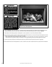
Step 2. Carefully remove the log set. Exercise
care as not to break the log set.
Step 3. Referring to Figure 66, remove the
burner.
Millivolt Appliances
Step 4. Refer to Figure 67 and the instructions
provided with the kit. Using a Torx T20 tool or
standard flat screwdriver, remove and discard
the three pressure regulator mounting screws.
Remove the pressure regulator, spring, poppet,
diaphragm and bushing. Discard all removed
components. Ensure the rubber gasket installed
on the back of the replacement pressure regulator
is properly positioned and install the new pressure
regulator using the new screws supplied with the
kit. Tighten screws to 25 In. lb. torque.
Figure 68
Pilot
Orifice
Figure 70