


NOTE: DIAGRAMS & ILLUSTRATIONS NOT TO SCALE.
2
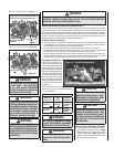
CONGRATULATIONS!
In selecting this LENNOX Direct-Vent Gas Appliance you have chosen the fi nest and most
dependable fi replace to be found anywhere. Its a beautiful, prestigious alternative
to a wood burning fi replace. Welcome to a Family of tens of thousands of satisfi ed
LENNOX Fireplace Owners.
Please carefully read and follow all of the instructions found in this manual. Please pay
special attention to the safety instructions provided in this manual. The Homeowner's
Care and Operation Instructions included here will assure that you have many years
of dependable and enjoyable service from your LENNOX product.
INTRODUCTION
The Fireplace models covered in this manual
are Direct-Vent sealed combustion gas fi replace
heaters designed for residential application.
Direct-Vent appliances operate with the com-
bustion chamber completely isolated from the
indoor environment. All air for combustion is
brought in from the outside and exhaust gases
are vented through the same direct vent, co-axial
(intake/exhaust) vent system.
The Millivolt appliances have a millivolt gas
control valve with piezo ignition system provides
safe, effi cient operation. If any optional acces-
sories which require electrical power are being
installed, the electrical power must be provided
at the time of appliance installation.
The Electronic appliances have an electronic
intermittent pilot system provides safe, effi cient
operation. External electrical power is required
to operate these appliances.
GENERAL INFORMATION
Note: Installation and repair should be per-
formed by a qualifi ed service person. The
appliance should be inspected annually by a
qualifi ed professional service technician. More
frequent inspections and cleanings may be
required due to excessive lint from carpeting,
bedding material, etc.
These appliances comply with National Safety
Standards and are tested and listed by OMNI-
Test Laboratories, Inc. (Report No.116-F-28-5)
to ANSI Z21.88a-2003 (in Canada, CSA-2.33a-
2003), and CAN/CGA-2.17-M91 in both USA and
Canada, as vented gas fi replace heaters.
The Installation must conform to local codes
or, in the absence of local codes, with the
National Fuel Gas Code, ANSI Z223.1/NFPA
54-latest edition, or the Natural Gas and
Propane Installation Code, CSA B149.1-latest
edition. The appliance, when installed, must
be electrically grounded in accordance with
local codes or, in the absence of local codes,
the latest edition of the National Electrical Code,
ANSI/NFPA 70, or the Canadian Electrical Code,
CSA C22.1 - latest editions.
TABLE OF CONTENTS
Introduction ......................................Page 2
General Information ..........................Page 2
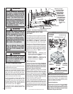
Gas Controls Access .........................Page 4
Operation / Care of Your Appliance ...Page 4
Variable Flame Adjustment ................Page 5
Maintenance ......................................Page 5
Front Glass Enclosure Panel,
Removal and Installation .................Page 6
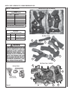
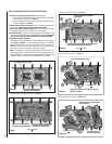
Install Grate, Vermiculite
Embers & Logs .................................Page 7
Burner Flame Appearance & Sooting Page 9
Burner Flame Adjustments ................Page 9
Millivolt Appliance Checkout .............Page 10
Electronic Appliance Checkout ..........Page 10
Wiring Diagrams ...............................Page 11
Warranty ...........................................Page 11
Product Reference Information .........Page 11
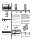
Accessory Components ....................Page 12
Lighting Instructions – Millivolt ........Page 15
Lighting Instructions – Electronic .....Page 16
Maintenance Schedule ......................Page 17
Troubleshooting Guide – Millivolt .....Page 18
Troubleshooting Guide – Electronic ..Page 18
Replacement Parts List .....................Page 20
IMPORTANT
It is imperative that the control
compartment, burners and circu-
lating air passage ways of appli-
ance be kept clean. See Mainte-
nance instructions on Page 5.
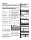
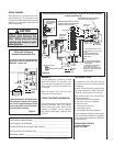
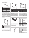
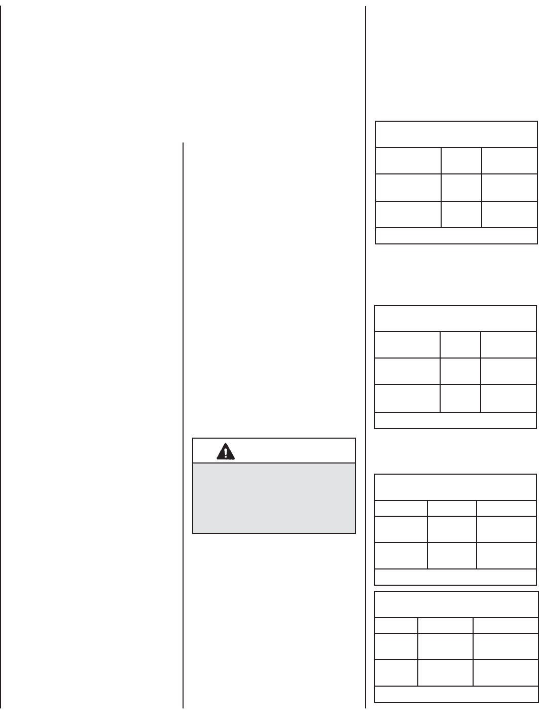
Electronic Models -
Electronic models have a fi xed rate gas valve.
The BTU Input for electronic models is shown
in Table 2:
Gas Pressure -
Tables 3, 4 and 5 show the appliances' gas
pressure requirements.
Inlet Gas Supply Pressure
(all models)
Fuel # Minimum Maximum
Natural Gas
5.0" WC
(1.24 kPa)
10.5" WC
(2.61 kPa)
Propane
11.0" WC
(2.74 kPa)
13.0" WC
(3.23 kPa)
Table 3
Input (BTU) - Fixed Rate
(electronic models)
Models Fuel
Type
Input Rate
(BTU / HR)
MPD35ST-NE Nat. Gas 30,000
MPD35ST-PE
(if fi eld converted)
Pro. Gas 28,000
Table 2
Manifold Gas Supply Pressure
(millivolt models)
Fuel # Low High
Natural
Gas
(Lo) 2.2" WC
(.55 kPa)
(Hi) 3.5" WC
(.87 kPa)
Propane
(Lo) 6.3" WC
(1.57 kPa)
(Hi) 10.0" WC
(2.49 kPa)
Table 4
Input (BTU) Manually-Modulated Gas
Valves (millivolt models)
Models Fuel
Type
Input Rate
(BTU / HR)
MPD35ST-NM Nat. Gas
30,000 high
23,000 low
MPD35ST-PM Propane
28,000 high
22,000 low
Table 1
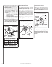
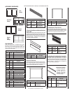
Provide adequate clearances around air open-
ings and adequate accessibility clearance for
service and proper operation. Never obstruct
the front openings of the appliance.
Due to high temperatures the appliance should
be located out of traffi c and away from furniture
and draperies. Locate furniture and window
coverings accordingly.
These fi replaces are designed as supplemen-
tal heaters. Therefore, it is advisable to have
an alternate heat source when installed in a
dwelling.
These appliances are designed to operate on natural
gas or propane gas only. The use of other fuels or
combination of fuels will degrade the performance
of this system and may be dangerous.
Millivolt Models - BTU Input
Millivolt models come standard with the manu-
ally-modulated gas valve; fl ame appearance and
heat output can be controlled at the gas valve.
The BTU Input for millivolt models is shown
in Table 1: