


11
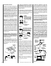
NOTE: DIAGRAMS & ILLUSTRATIONS ARE NOT TO SCALE.
PRODUCT REFERENCE INFORMATION
Cat.
No.
Model Ship
Weight
Ship.
Volumn
H3201 MPD35ST-NM 220 lbs 46W x 26D x
43H (30 cu.ft.)
H3202 MPD35ST-PM 220 lbs 46W x 26D x
43H (30 cu.ft.)
H3203 MPD35ST-NE 220 lbs 46W x 26D x
43H (30 cu.ft.)
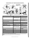
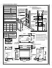
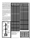
FIREPLACE SPECIFICATIONS - MPD35ST
NOTES
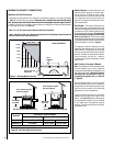
• Annual Fuel Utilization Efficiency
Due to Lennox' ongoing commitment to quality,
all specifications, ratings and dimensions are
subject to change without notice.
Appliance has a factory-installed vent seal cap
(see Figures 16 & 17 on Page 14) in each flue
outlet.
EFFICIENCIES
61 % Natural Gas
62 % Prop. Gas
• AFUE
65 % Natural Gas
67 % Propane Gas
SPECIFICATIONS
Natural Gas BTU Input 30,000
Propane Gas BTU Input 28,000
Co-axial DV Vent Size
4-1/2" Inner /
7-1/2" Outer
5-5/8
(143)
***39-7/8
(1013)
35-1/4
(895)
**20-3/4
(527)
10-1/2
(267)
12-1/8
(308)
5-1/8
(130)
12-1/8
(308)
25-1/2
(648)
5-1/8
(130)
Vent Center - Top Vent
with one 90 degree
elbow
Vent Center - Side Vent
with no elbows
Secure Vent
42-3/4 (1086)
Secure Flex
43-1/2 (1105)
**This dimension
based on 5/8" drywall.
For 1/2" drywall use
21" (533 mm). The
finished dimension
should be 22" (558
mm)
• Inches (millimeters)
•
Minimum Framing Stud Size is 2 x 4
• See
side views of fireplace below
for
gas line inlet location options.
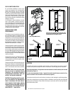
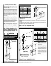
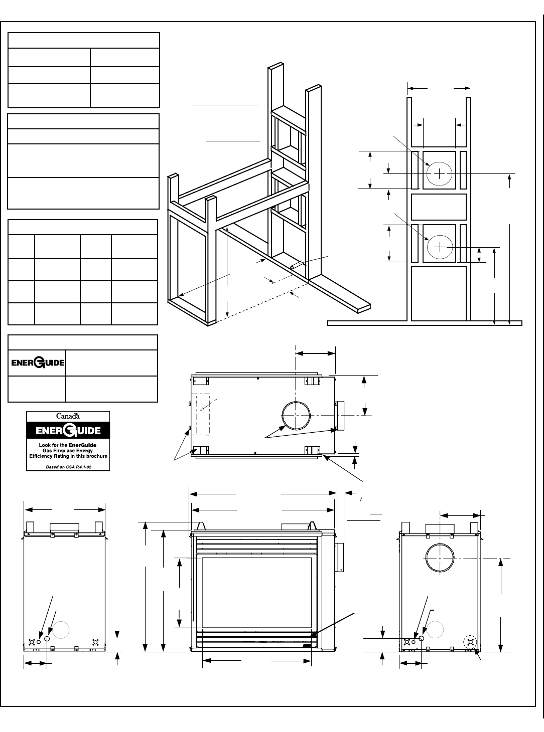
Fireplace Framing Specifications
Center of gas line
is 3-1/8 inches
(79 mm) up from
floor.
Notes:
***This dimension does
not include the addition
of drywall to the inside of
framing or clearance for
the Side Vent Seal Cap.
Adjust accordingly for your
installation.
See also, Side Vent Seal Cap
note below.
Louvered Control
Compartment Door
Gas Inlet
Control Switch Wires
Knock-Out
Gas
Inlet
Framing Spacers
(top and both sides)
Stepped to Accept Drywall
Vent Seal Cap
Top View
Front View
Left Side View
Right Side View
Control Switch Wires
Knock-Out
Optional
Blower
Provide additional
space for Side
Vent Seal Cap if
installing against a
solid wall.
22
(559)
35-1/8
(892)
32-5/8
(827)
19
(483)
29 1/2
(749)
39-3/4 (984)
3 (76)
38-3/8 (899)
10-7/8 (264)
11 (279)
(16)
11 (279)
6-1/4
(159)
6-1/4
(159)
25-1/2
(646)
3-1/8 (79) 3-1/8 (79)
5/8
Junction Box Knock-Out
(2 places each side)
Figure 13
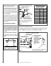
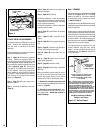
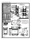
Vertical Venting Through the Ceiling:
Frame ceiling opening - Use a plumb line
from the ceiling above the appliance to
locate center of the vertical run. Cut and/or
frame an opening, 10-1/2" x 10-1/2" (267
mm x 267 mm) inside dimensions, about
this center mark (see Figure 20).