


16
NOTE: DIAGRAMS & ILLUSTRATIONS ARE NOT TO SCALE.
WARNINGS
• Air shutter adjustment should
only be performed by a quali-
fied professional service tech-
nician.
• Ensure front glass panel are
in place and sealed during
adjustment.
CAUTIONS
• Soot will be produced if the
air shutter is closed too much.
Any damage due to sooting,
resulting from improperly
setting the air shutter, is not
covered under the warranty.
• The air shutter door and
nearby appliance surfaces
are hot. Exercise caution to
avoid injury while adjusting
flame appearance.
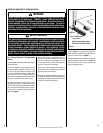
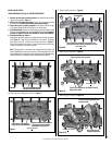
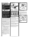
1. Refer to Figure 13 for proper flame ap-
pearance. To adjust the flame, rotate the
adjustment rod toward the back or toward
the front of the fireplace (rod located in
the lower control area). Position the air
shutter to the factory setting as shown in
the table in Figure 14.
2. Light appliance (follow lighting procedure
on lighting label in control compartment
or see the Care and Operation Manual).
3. Allow the burner to operate for at least 15
minutes while observing the flame con-
tinuously to ensure that the proper flame
appearance has been achieved. If the
following conditions are present, adjust
accordingly.
• Ifameappearsweakorsooty,adjust
the air shutter, incrementally, to a
more open position until the proper
flame appearance is achieved.
• Ifameremainsblue,adjusttheair
shutter, incrementally, to a more
closed position until the proper flame
appearance is achieved.
4. Leave the control knob (off/pilot/on) in
the ON position and the burner OFF/ON
switch OFF (and remote switches, if ap-
plicable).
5. When satisfied that the burner flame ap-
pearance is normal, re-install the lower
control compartment door then proceed
to finish the installation.
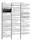
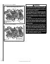
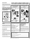
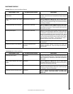
MILLIVOLT
Thermocouple
Hood Igniter Rod
3/8" Min
(9 mm)
Thermopile
Pilot
Nozzels
Millivolt Appliance Checkout
The pilot flame should be steady, not lifting
or floating. Flame should be blue in color with
traces of orange at the outer edge.
The top 3/8" (10 mm) at the pilot generator
(thermopile) and the top 1/8" minimum (tip)
of the quick drop out thermocouple should be
engulfed in the pilot flame.
The flame should project 1" (25 mm) beyond the
hood at all three ports (see Figure 15 ). Replace
logs if removed for pilot inspection.
To light the burner; turn “ON” the remote wall
switch and rotate the gas valve control knob
counterclockwise to the “ON” position (“ON”
will be at the top side of the valve).
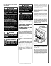
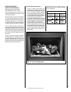
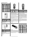
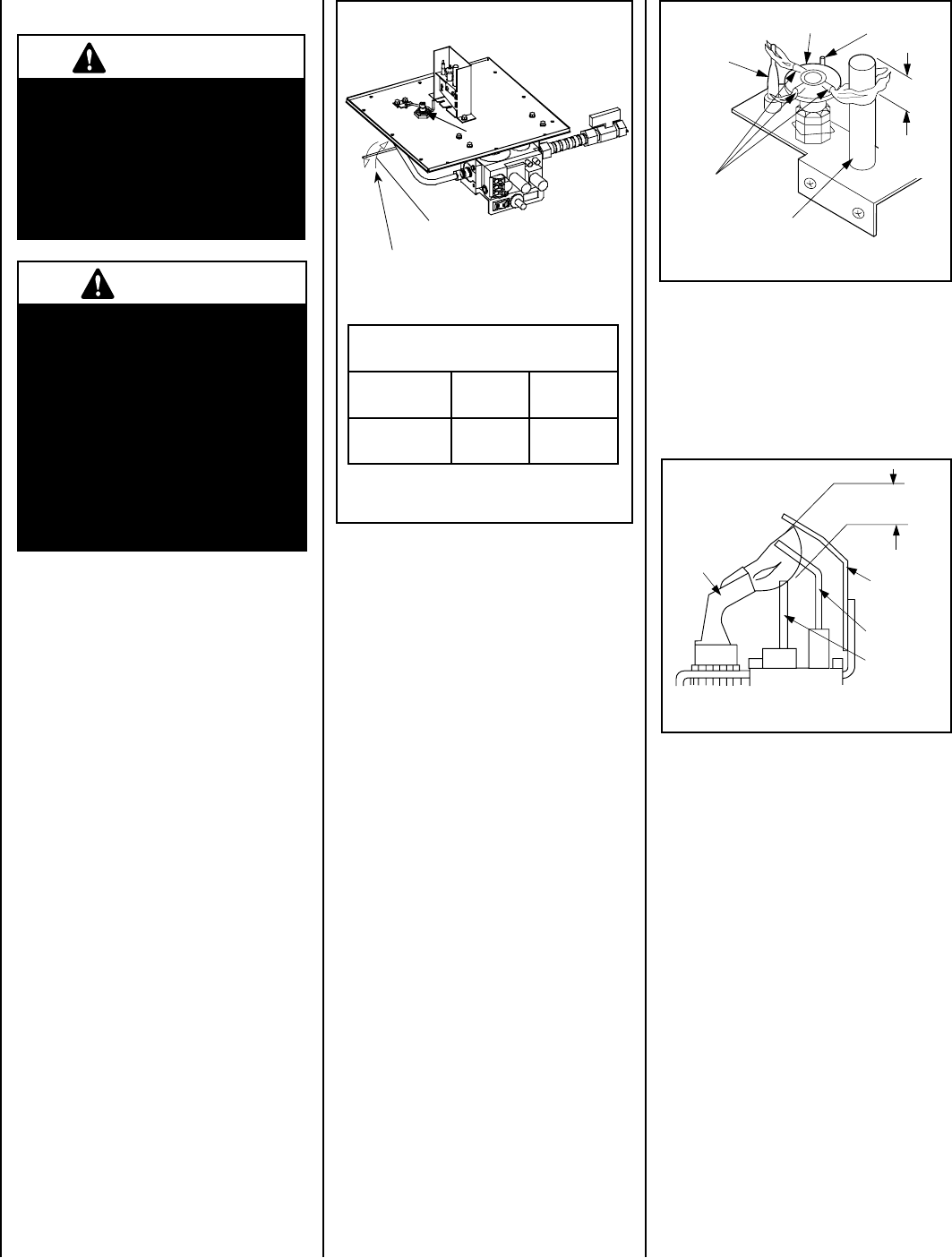
Electronic Appliance Checkout
To light the burner, turn ‘ON’ the unit mounted
On/Off switch or the optional remote wall switch.
Ensure the igniter lights the pilot. The pilot
flame should engulf the flame rod as shown
in Figure 16.
Figure 15
ELECTRONIC
Proper Flame
Adjustment
Pilot
Nozzle
3/8 To 1/2 Inch
(9 mm to 13 mm)
Ground
Electrode
Flame Rod
Hot Surface
Igniter
Figure 16
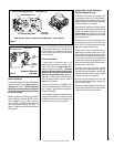
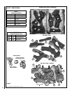
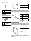
BURNER FLAME ADJUSTMENTS
Adjustment Rod Positions
(when viewed from above)
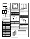
Figure 14
Main Burner Factory Air Shutter
Opening Setting - All Models
Model Natural
Gas
Propane
Gas
MPD35ST/PF
1/8”
3.2mm
1/4”
6.4mm
Air Shutter
Adjusting Rod
Increase Shutter Opening
In This Direction
Decrease Shutter Opening
In This Direction
Note - Burners are omitted in this view for clarity.
Orifice
Ref. Air shutter Patent:
U.S. Pat. 5,553,603