8
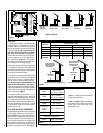
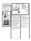
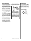
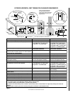
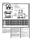
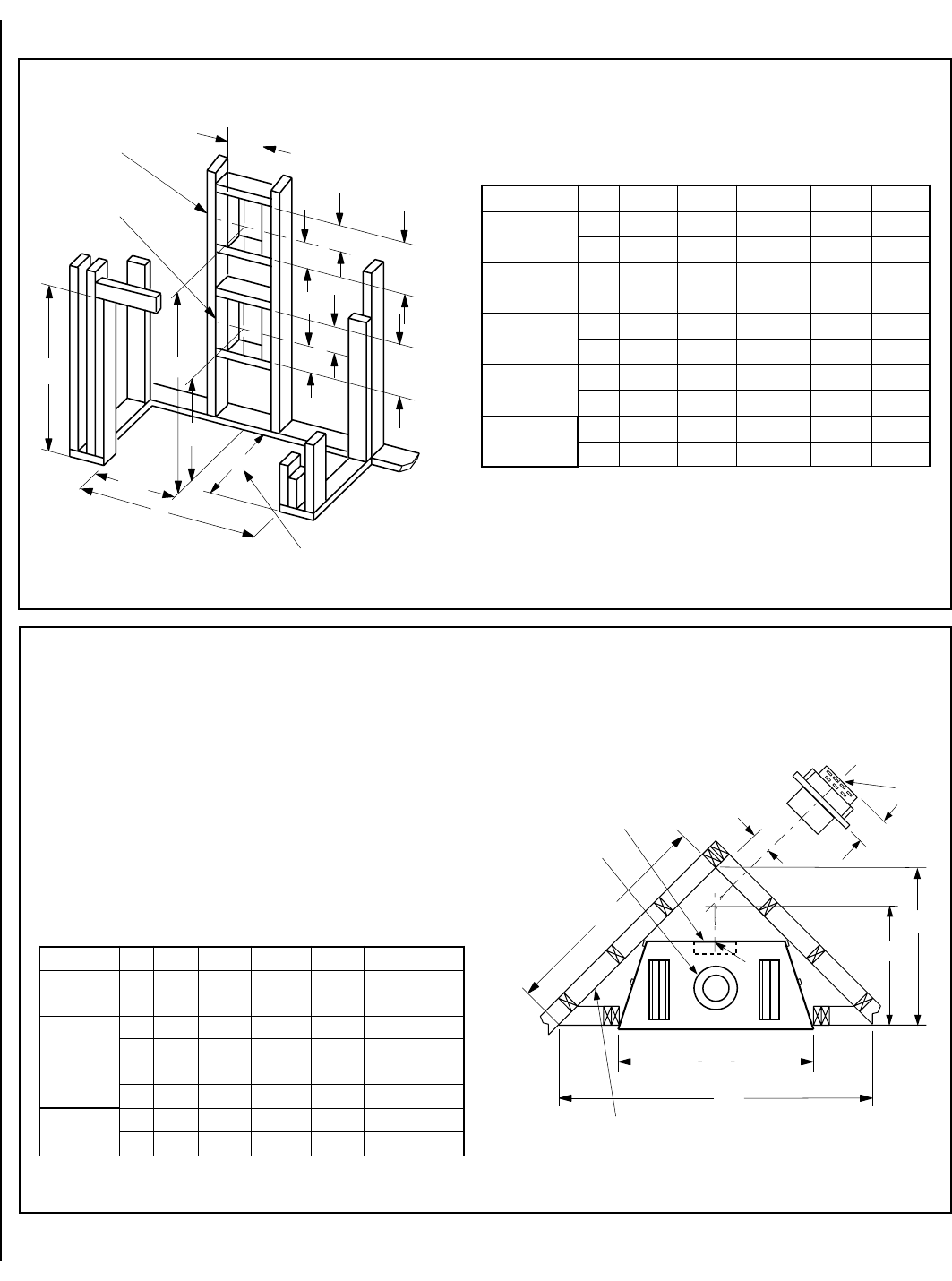
NOTE: DIAGRAMS & ILLUSTRATIONS NOT TO SCALE.
.oNledoMABCDEF
8233-TDPM
8233-RDPM
.ni8/1332/18461/54361/3714/1425
mm1482321278734616721
0353-DPM
.ni8/1532/1758/50461/3914/3828/16
mm29816412301784037651
5304-DPM
.ni8/10461/31623/113461/39161/11038/77
mm910145511011784977002
0454-DPM
.ni8/1548/36661/516461/39161/3334/39
mm641168612911784348842
C
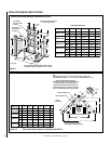
Back wall of chase/enclosure
(including any finishing materials)
a
7 (178)
b
Note-
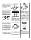
Venting requirements for rear vent applications in corner installations -
- the horizontal vent length “a” to “b,” must not exceed 28 inches (711 mm)
Inches
(millimeters)
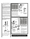
MPDT-3328 AND MPDR-3328 Models -
Dimensions A to F occur when one 45 degree elbow
is connected directly to the appliance collar.
MPD-3530, MPD-4035 and MPD-4540 Models -
Dimensions D and F occur when one 45 degree
elbow is connected directly to the appliance collar.
MPD and MPDR units
D
E
F
A
B
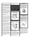
MPD and MPDT units
.oNledoMABCDE
8233-TDPM
.ni4/1334/133-----4/3738/721
mm548548-----959723
8233-RDPM
.ni4/1334/1338/591-----8/721
mm548548894-----723
0353-DPM
.ni4/1534/15361/11124/39361
mm5985981550101604
5304-DPM
.ni4/1044/10461/11624/34461
mm220122018767311604
0454-DPM
.ni4/1544/10461/11624/34461
mm941122018767311604
A
B
D
7
(178)
5-1/8
12-1/8
(308)
10-1/2
(
267
)
C
VENT FRAMING -
TOP VENT WITH ONE
90° ELBOW
VENT FRAMING -
REAR VENT WITH
NO ELBOWS
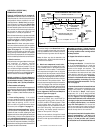
Framing should be constructed
of 2x4 or larger lumber.
Inches (mm)
E
(130)
(130)
7
(308)
(178)
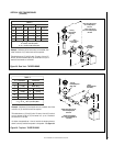
E is the required framing depth dimension when the
finish material (drywall) thickness is 1/2 in. (13mm).
1/2
A
FRAMING WITH SQUARE HORIZONTAL TERMINATION (SV4.5HT-2)
5-1/8
12-1/8
Figure 9
Figure 10
Framing Dimensions
FIREPLACE FRAMING SPECIFICATIONS
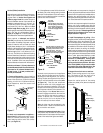
Corner Framing with Square Termination (SV4.5HT-2)


