


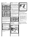
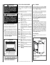
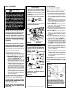
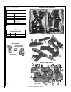
Figure 14
Thermopile
TH
TP
TH
TP
White
White
Black
Spill Switch
If any of the original wire as supplied must
be replaced, it must be replaced with Type
AWM105 C - 18 gage wire.
* Optional Kits - OFF/ON wall switch or
remote control receiver.
Millivolt Wiring Diagram
Appliance mounted OFF / ON Switch
Schematic Represen-
tation Only
Field Wired
Factory
Wired
12
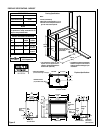
NOTE: DIAGRAMS & ILLUSTRATIONS ARE NOT TO SCALE.
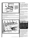
B. Electronic Wiring
(also see Figure 18 on Page 13)
Note: The electronic appliance must be con-
nected to the main 120 VAC power supply.
1. Locate the Electrical Outlet Kit provided (pack-
aged in firebox - contents: junction box, 2
screws, an receptacle outlet, a snap bushing
and an OFF/ON rocker switch - for millivolt
units only).
Note: The junction box can be installed in any
of the 4 outside corners of the control com-
partment (outlet installed in front left corner is
shown in Figure 17 ).
2. Route a 3-wire, 120 VAC, 60 Hz, 1 ph power
supply to the location on appliance where
junction box is to be installed.
3. Open the control compartment access panel
(see Control Compartment Access Instruc-
tions on Page 14).
4. Wire and install the outlet receptacle to
junction box, then install into the chosen
corner of the control compartment as shown
in Figure 17.
5. After the receptacle/junction box wiring is
complete, install the field-provided metal
junction box cover plate (see Figure 17).
6. Install the snap bushing (provided in kit)
into the selected cabinet knockout opening
in side cabinets (see Electrical Inlets, Figure
9 on Page 9). The snap bushing provides
protection for the wires (see note below)
passing through side cabinet going to an
optional burner control switch Wire in the
burner control switch to the low voltage circuit
as shown in Figure 18.
Note: The supplied 15 feet of 2 conductor
wire has one end of each conductor con-
nected to the gas valve circuit and the other
end of each conductor placed loose on top
of the appliance.
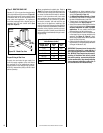
Important Note: The gas valve OFF/ON switch
is shown in Figure 18 on Page 13. It is integral
with the gas valve and should be set to the ON
position.
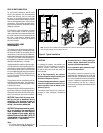
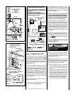
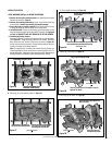
Gas
Valve
Control Compartment
Access panel
OFF/ON
Switch
TP TH
TH
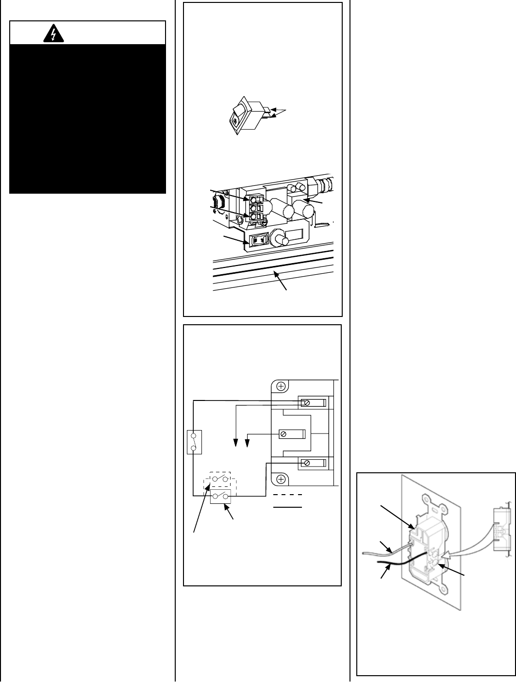
Install OFF/ON Switch
(millivolt models)
1. Connect the 2 wires (provided in Electrical
Outlet Kit) to the TP/TH and TH terminals
on valve.
2. Pass the 2 wires through the opening where
OFF/ON switch will be installed (left of piezo,
below valve).
3. Connect the two wires to the OFF/ON Switch.
OFF/ON
Switch
Connect
wires to
terminals
4. Press the OFF/ON switch into bracket as shown
below (it will snap into place).
Figure 13
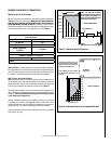
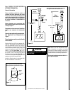
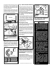
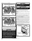
Note: Supply wires may be alternatively con-
nected to the outlet using the screw terminals,
however the black supply wire must be wired to
a terminal that is opposite (across the outlet) the
point where the white supply wire is connected.
Bipolar
Terminal
Screw
Ground Wire
Connection
White
(supply)
Black
(supply)
Figure 15
Step 4. FIELD WIRING
CAUTION
Ground supply lead must be con-
nected to the wire attached to the
green ground screw located on the
outlet box. See
Figure 18. Failure to
do so will result in a potential safety
hazard. The appliance must be
electrically grounded in accordance
with local codes or, in the absence of
local codes, the National Electrical
Code, ANSI/NFPA 70-latest edition.
(In Canada, the current CSA C22-1
Canadian Electrical Code).
CAUTION: Label all wires prior to disconnec-
tion when servicing controls. Wiring errors can
cause improper and dangerous operation.
ATTENTION: Au moment de l'entretien des
commandes, étiquetez tous les fils avant de
les débrancher. Des erreurs de cáblage peu-
vent entraîner un fonctionnement inadéquat
et dangereux.
Verify proper operation after servicing.
S'assurer que l'appareil fonctionne adé-
quatement une fois l'entretien terminé.
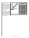
Refer to Section A for millivolt appliances and
Section B for electronic appliances.
A. Millivolt Wiring (See Figure 14) –
1. Install and wire in the burner control switch
(install either "a" or "b" below, NOT BOTH)
a. Standard OFF/ON Switch - Install the OFF/
ON burner control switch (rocker switch)
as shown in Figures 13 and 14.
b. Optional Control Switch (OFF/ON wall
switch or remote control receiver). Install
snap bushing (provided in Electrical
Outlet Kit) into control switch knock-out in
side panel (see Figure 9 on Page 9). Wire
the optional control switch within the mil-
livolt control circuit (as shown in Figure
14) using the 15 feet of 2 conductor wire
supplied (route wires through the snap
bushing to the optional control switch).
Mount the optional control switch or wall
thermostat in a convenient location on a
wall near the fireplace.
CAUTION: DO NOT CONNECT OPTIONAL CON-
TROL SWITCH TO 120 V POWER SUPPLY.
CAUTION: REMOVE THE CARTON SUPPORT
FROM THE CONTROL COMPARTMENT BEFORE
OPERATING THE APPLIANCE.
CAUTION: ENSURE THAT WIRES ARE POSI-
TIONED AWAY FROM HOT SURFACES AND
SHARP EDGES.