


8
NOTE: DIAGRAMS & ILLUSTRATIONS ARE NOT TO SCALE.
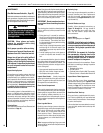
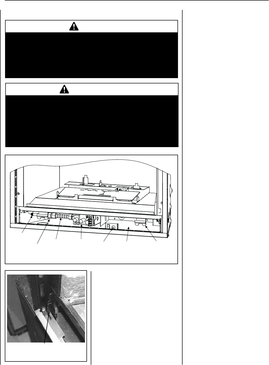
Main Gas Shut-Off Valve
LENNOX HEARTH PRODUCTS • MERIT
®
SERIES DIRECT-VENT GAS FIREPLACES • MODELS MLDVT-30/35/40/45 • CARE AND OPERATION INSTRUCTIONS
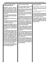
Gas Controls/Control Compartment
Access
The gas controls can be found behind the control
compartment access door.
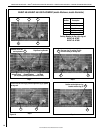
Removing Control Compartment Door:
Open the panel by gently lifting it upward and
forwards. Slide the door, first to one side and
then the other, so the tabs clear both of the
locating holes.
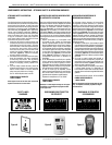
OPERATION AND CARE OF YOUR APPLIANCE
WARNING
Young children should be carefully supervised when they are in the
same room as the appliance. Toddlers, young children and others
may be susceptible to accidental contact burns. A physical barrier is
recommended if there are at risk individuals in the house. To restrict
access to a fireplace or stove, install an adjustable safety gate to keep
toddlers, young children and other at risk individuals out of the room
and away from hot surfaces.
AVERTISSEMENT
Les jeunes enfants devraient être surveillés étroitement lorsqu’ils se trou-
vent dans la même pièce que l’appareil. Les tout petits, les jeunes enfants
ou les adultes peuvent subir des brûlures s’ils viennent en contact avec
la surface chaude. Il est recommandé d’installer une barrière physique
si des personnes à risques habitent la maison. Pour empêcher l’accès
à un foyer ou à un poêle, installez une barrière de sécurité; cette mesure
empêchera les tout petits, les jeunes enfants et toute autre personne à
risque d’avoir accès à la pièce et aux surfaces chaudes.
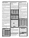
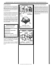
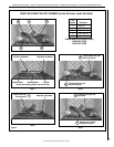
Figure 1
Gas Flex Line
3 Inch
Pipe Nipple
Valve
Piezo
Spring Door
Latch
Lower Control
Compartment
On millivolt systems, the piezo igniter, HI/LO
ame adjustment knob, and pilot and main
gas OFF/ON control knob are located below
the glass panel enclosure. The gas valve for
electronic systems is also located below the
glass enclosure panel (see Figure 1).
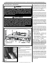
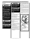
Reinstalling Control Compartment Door:
To reinstall, insert the tabs on each side of the
door into the corresponding holes in the control
compartment opening, one side first then the
other. To close, pull the door gently up and
close by pushing forward and pushing the top
edge down into the groves at the brackets until
it locks in place.
The standard controls for appliance operation
are located behind the panel below the appli-
ance front glass enclosure panel (Figure 1).
Optional control switches are also available
(see Page 18 - Remote Wall Switch, Remote
Control, Unit Mounted Rocker Switch or Wall
Thermostat).
Operation of millivolt and electronic gas con-
trol systems are different. Before lighting and
operating your appliance determine if you have
a millivolt or electronic appliance. Familiarize
yourself with the gas control valve that your
appliance uses. Refer to Figure 1 for access to
the gas control valve.
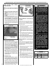
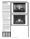
Millivolt Appliances - Appliances with
Millivolt systems will be tted with the gas
control valve shown in Figure 3.
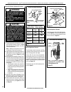
Electronic Appliances - Appliances with
electronic systems will be fitted with the
electronic valve shown in Figure 4.
Millivolt Appliances - To light millivolt ap-
pliances refer to Figure 1. Detailed lighting
instructions are found on Pages 21 and 22.
Millivolt appliance lighting instructions may
also be found on the pull out lighting instruction
labels attached to the gas control valve.
Once the pilot is lit, the main burner may be
turned ON and OFF using a wall switch, remote
control, optional on unit rocker switch (FRS),
or wall thermostat. To operate: Toggle the
switch between its ON and OFF positions.
If your millivolt appliance is equipped with an
optional remote switch kit (wall switch, remote
control, rocker switch, or wall thermostat) and
the pilot is lit, the appliance main burner may be
turned on and off using the optional switch.
Note: To prevent excessive resistance in burner
circuit (which can cause burner operation prob-
lems), only one burner control switch should
be wired to valve.
Figure 2
Control Compartment Door Tab