


9
NOTE: DIAGRAMS & ILLUSTRATIONS NOT TO SCALE.
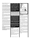
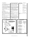
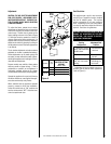
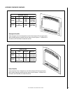
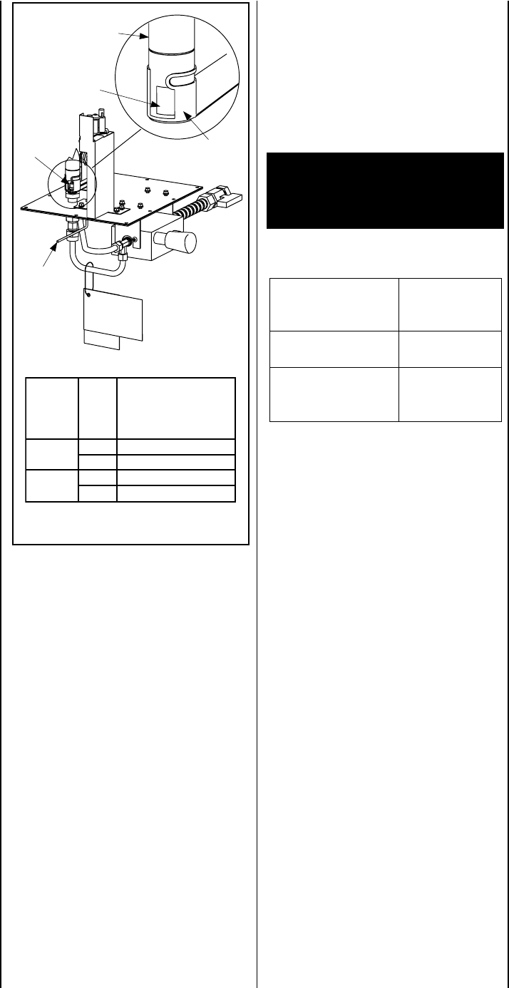
Figure 8
sledoM
saG
epyT
RIAYROTCAF
GNITTESRETTUHS
GNINEPO
)mm(sehcni
53-SSL
.taN2/1)0.31(
.porP8/5)8.51(
04-SSL
.taN2/1)0.31(
.porP8/5)8.51(
Air Shutter
Opening
Burner
Venturi
Tube
Air
Shutter
Door
Orifice
Air Shutter
Adjusting
Rod
Adjustment
CAUTION: THE AIR SHUTTER ADJUSTMENT
ROD (
SEE FIGURE 8
) AND NEARBY APPLI-
ANCE SURFACES ARE HOT. EXERCISE CAU-
TION TO AVOID INJURY WHILE ADJUSTING
FLAME APPEARANCE.
To adjust the flame, restate the air shutter
adjustment rod toward the back or toward the
front of the fireplace (rod located in the lower
control area). Position the air shutter to the
factory setting as shown in the Table of
Figure
8
. Allow the burner to operate for at least 15
minutes. Observe the flame continuously. If it
appears weak or sooty as previously described,
adjust the air shutter by pushing or pulling on
the adjustment rod until the flame appearance
is as desired.
The air shutter adjustment rod and associated
adjustable air shutter is patented technology.
Flame adjustments can be made quickly and
accurately to taste without the need of disas-
sembling the appliance and waiting for 30 min-
utes after each adjustment.
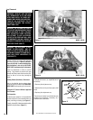
Propane models may exhibit a flame pattern
that may candle or appear stringy. If this is
problematic or persists as the appliance is
continually operated, adjust the air shutter
closed as described in the previous paragraphs.
Operate the appliance for a period of time as
the effect diminishes, ensuring that the appli-
ance does not develop sooty flames.
When satisfied that the appliance operates
properly, proceed to finish the installation.
Leave the control knob in “ON” position and
turn the remote switch “OFF.” Close the lower
control compartment door.
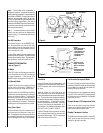
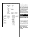
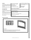
Vent Restrictor
The appliance has a built-in vent restrictor,
refer to
Figure 7, page 8
for location, to adjust
the flow of exhaust gases. This ensures
proper combustion for all vent configura-
tions. Depending on the vent configuration,
you may be required to adjust the restriction
position. See below for guidelines.
* Adjustment to the air shutter may be re-
quired to get the desired flame appearance,
(
refer to
Figure 8
).
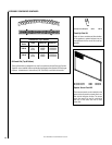
1. Horizontal Venting
with 6" vent section and
one 90° elbow.
* Pointed toward
the front.
2. Vertical venting.
3. Combination of ver-
tical and horizontal
venting.
* Pointed toward
the left.
* Adjust
accordingly for
best result.
Venting
Configuration
Adjustment Rod
Position
CAUTION: THE FIREPLACE NEEDS TO BE ON
DURING THE ADJUSTMENT OF THE VENT
RESTRICTOR. USE A GLOVE TO PROTECT
YOUR HAND FROM BURNS.