


NOTE: DIAGRAMS & ILLUSTRATIONS ARE NOT TO SCALE.
21
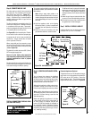
WARNING
Never use an open flame to
check for leaks.
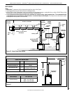
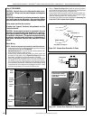
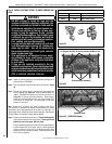
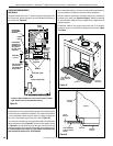
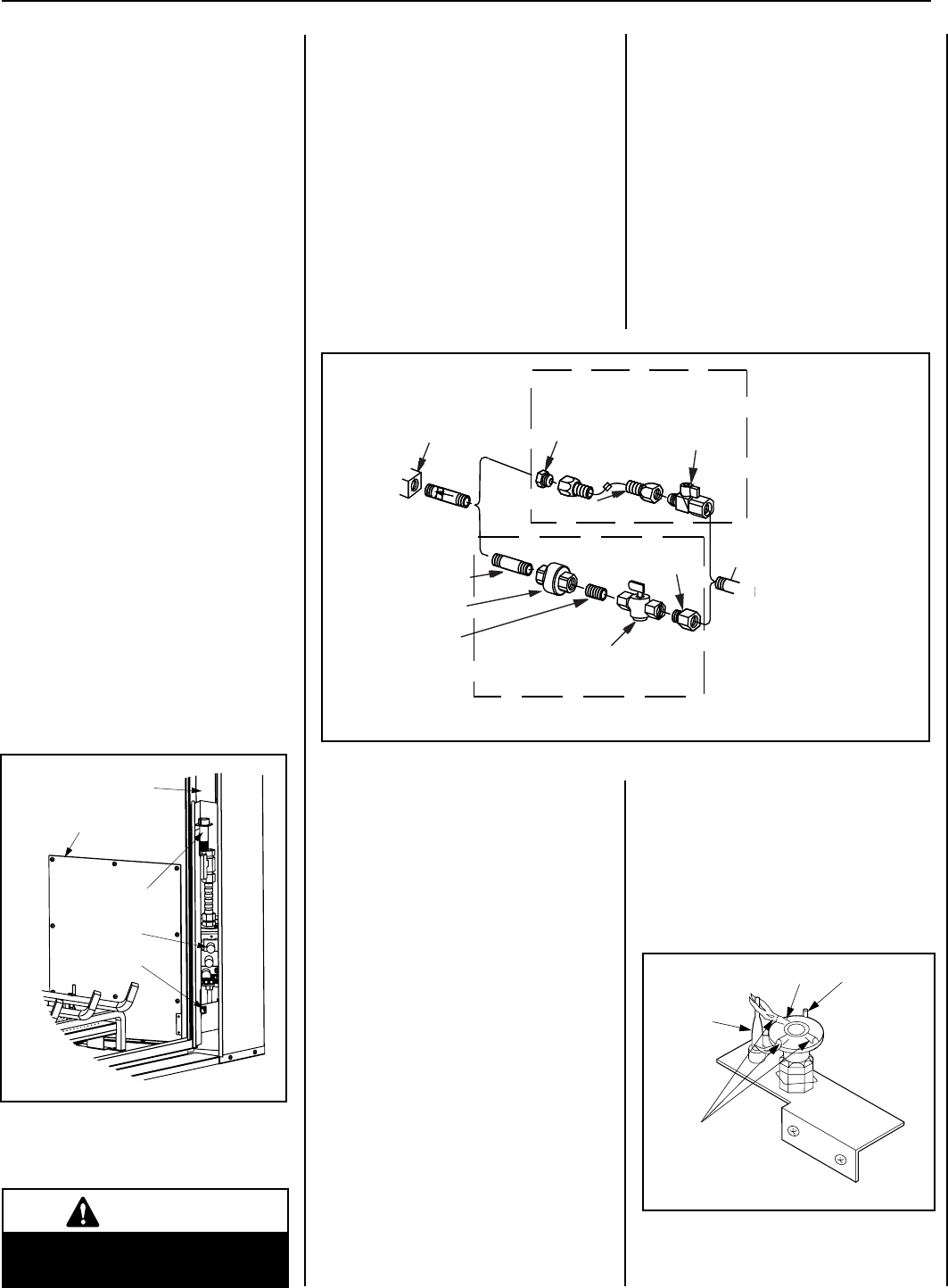
Step 6. CONNECTING GAS LINE
All codes require a shut-off valve mounted in
the supply line. The orientation of the shut-off
valve should face the front. Figure 29 il-
lustrates two methods for connecting the gas
supply. A Sediment Trap is recommended to
prevent moisture and debris in gas line from
damaging the valve.
The ex-line method is acceptable in the U.S.A
where local codes permit. Installation must be
in compliance with local codes. These appli-
ances are equipped with a gas ex-line for use
in connecting the unit to the gas line.
See Figure 29 for ex-line description. The ex-
line is rated for both natural and propane gas.
A manual shut off valve is also provided with
the ex-line. The gas control valve is located
on the right side of the unit.
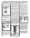
When using solid gas line connector, access
the valve by removing the front door assembly
on the valve access side and the access plate
(refer to Figure 28).
The electronic control valve has a 3/8" (10 mm)
NPT thread gas supply inlet.
Secure all joints tightly using appropriate
tools and sealing compounds (ensure propane
resistant compounds are used in propane
applications).
Bring the shutoff valve on the end of the ex-line
over to the hard pipe and tighten with wrenches
from above through the rebox opening.
Turn on gas supply and test for gas leaks using a
gas leak test solution (also referred to as bubble
leak solution).
Note: Using a soapy water solution is an
effective leak test solution but it is not recom-
mended, because the soap residue that is left
on the pipes/fittings can result in corrosion
over time.
A. Light the appliance (refer to the lighting
instructions label in control compartment
or in the Care and Operation instructions
manual).
B. Brush all joints and connections with the
gas leak test solution to check for leaks.
TEST ALL CONNECTIONS FOR GAS LEAKS
(FACTORY AND FIELD):
If bubbles are formed, or gas odor is detected,
turn the gas control knob (off/pilot/on) to the
“OFF” position. Either tighten or refasten the
leaking connection, then retest as described
above.
C. When the gas lines are tested and leak free
be sure to rinse off the leak testing solution.
D. Re-install the access plate, making certain
the gasket has not been damaged.
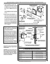
Step 7. INSTALL FIREBOX LINER KIT
Install the rebox liner kit per the instructions
provided in kit (ref form # 750182M).
Figure 28
Note: The gas supply line
must be installed in accor-
dance with building codes
by a qualified installer
approved and/or licensed
as required by the locality.
In the Commonwealth of
Massachusetts, installation
must be performed by a
licensed plumber or gas
fitter.
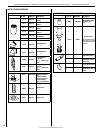
Gas
Valve
3/8" NPT x
Flare Fitting
3/8" Flex Tubing
3/8" Nipple
3/8" Union
3/8" Close
Nipple
3/8" Shut-off Valve
1/2" x 3/8"
Reducer
Gas
Stub
1/2" x 3/8" Flare
Shut-off Valve
Gas Solid Line Connector
Gas Flex Line Connector
*Sediment
Trap
3"
Min
Figure 29 - GAS CONNECTION
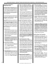
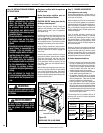
ELECTRONIC
Flame
Sensor
Hood
Igniter Rod
Pilot
Nozzels
Right Side
Modesty Panel
Access Plate
Hi-Lo
Extension Knob
ON/OFF Switch
Gas Valve
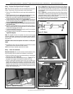
Figure 30
LENNOX HEARTH PRODUCTS • MONTEBELLO
®
POWER VENT DV GAS FIREPLACES (LSM40/45EN-PV) • INSTALLATION INSTRUCTIONS
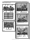
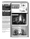
Step 8. VERIFYING APPLIANCE OPERA-
TION
Turn on burner then observe the individual
tongues of ame on the burner. Make sure
all ports are open and producing flame evenly
across the burner. If any ports are blocked, or
partially blocked, clean out the ports.
With gas line installed run initial system check-
out before closing up the front of the unit.
Follow the pilot lighting instructions provided.
Note: Lighting Instructions are also found on
the literature tag tied to the bracket above the
gas valve. To access the tag, reach into the
right side opening.
When first lighting the appliance, it will take
a few minutes for the line to purge itself of
air. Once purging is complete, the pilot and
burner will light and operate as indicated in
the instruction manual. Subsequent lighting
of the appliance will not require such purging.
Inspect the pilot flame (remove logs, if neces-
sary, handling carefully).
Electronic Appliance Checkout
To light the burner, turn ‘ON’ the optional remote
wall switch or turn the appliance mounted ON/
OFF switch to the “ON” position. Ensure the
igniter lights the pilot. The pilot flame should
engulf the flame sensor as shown in Figure 30.