


6
NOTE: DIAGRAMS & ILLUSTRATIONS NOT TO SCALE.
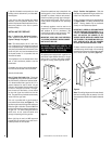
Step 3. Position the Appliance - Slide the
fireplace into prepared framing or position fire-
place in its final position and frame later.
Refer to fireplace drawings and specifications
on pages 4 and 5 for framing dimensions and
details. Framing header may be positioned
directly on the fireplace top spacers.
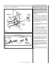
IMPORTANT: UNDER NO CIRCUMSTANCES
CAN THE FIREPLACE TOP SPACERS
(refer to
FIGURE 2 )
BE REMOVED OR MODIFIED, NOR
MAY YOU NOTCH THE HEADER TO FIT
AROUND OR BE INSTALLED LOWER THAN
THE SPACERS. THE HEADER MAY BE IN DI-
RECT CONTACT WITH THE TOP SPACERS
BUT MAY NOT BE SUPPORTED BY THEM.
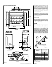
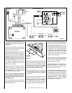
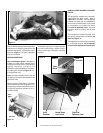
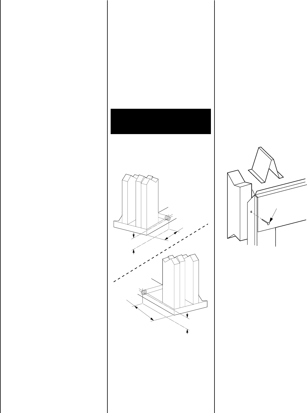
Fireplace should be secured to side framing
members using the full length 1/2 inch nailing
flanges that are integral to the appliance at each
side. Use 6d nails or equivalent
(Figure 9 )
.
All appliances are equipped with a gas flex line
and shutoff valve attached directly to the gas
control valve. To quickly and easily complete
the gas line routing, use the gas flex line kit.
4. Use this information and consult your local
building code to determine if you need addi-
tional support.
If you plan to raise the fireplace and hearth
extension, build the platform assembly then
position fireplace and hearth extension on top.
Secure the platform to the floor to prevent
possible shifting.
INSTALLING THE FIREPLACE
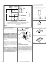
Step 1. Construct the Appliance Framing -
Frame appliance enclosure as illustrated in
Figures 4 through 7
on page 5.
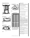
Note: The framed depth, 20-1/2" (521 mm)
from a framed wall, must always be measured
from a finished surface. If a wall covering such
as drywall is to be attached to the rear wall, then
the 20-1/2" (521 mm) must be measured from
the drywall surface. It is important that this
dimension be exact.
If the appliance is to be elevated above floor
level, a solid continuous platform must be
constructed.
The header may rest on the top metal spacers,
but must not be notched to fit around them.
Consult all local codes.
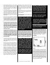
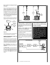
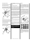
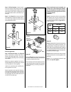
Step 2. Route Gas Supply Line - Route gas
line
(Figure 8 )
using techniques and materi-
als prescribed by local and/or national codes.
It is recommended that a gas line of 1/2" or
greater diameter be used to allow full gas
volume to the fireplace. Undue pressure loss
will occur if the pipe is too small. The appli-
ance, as set up at the factory, is best suited
for use with a gas line routed from the left
side. The gas line may however be alternately
routed from the right side.
This unit is provided with a gas line/switch
wire outlet at both sides (see
Figure 2
). The
gas line may be routed through this opening at
either the right or left side. Route the Millivolt
switch wire through the opening opposite form
the gas line. To avoid cutting the Millivolt
switch wire, do not route the switch wire
through the opening with the gas line.
When rigid pipe is used, an ANSI approved
manual shut-off valve and union must be in-
stalled upstream of the fireplace.
IMPORTANT: HOLD GAS VALVE SECURELY
TO PREVENT MOVEMENT WHEN CONNECT-
ING TO INLET GAS LINE
An external regulator must be used on all
propane (L.P.G.) heaters to reduce the supply
tank pressure to 13" w.c. (maximum). Any
copper tubing used to supply propane (L.P.G.)
from the tank must be internally tinned.
Note: The nailing flanges and the area directly
behind the nailing tabs are exempt from the
clearances described on the fireplace clearance
label.
Figure 8
Figure 9
10-1/2"
(269 mm)
3-1/2"
(79 mm)
RIGHT
SIDE
LEFT
SIDE
7-1/4"
(184 mm)
3-1/2"
(79 mm)
WARNING: CONNECTING DIRECTLY TO
AN UNREGULATED PROPANE (L.P.G.)
TANK MAY CAUSE AN EXPLOSION.
6d Nail or
Equivalent
Ensure that a sediment trap is installed in the
existing gas line, if not, install a sediment trap
upstream to prevent moisture and contami-
nants from passing through trap to the appli-
ance controls and burners. Failure to do so
could prevent the appliance from operating
reliably.