


7
NOTE: DIAGRAMS & ILLUSTRATIONS NOT TO SCALE.
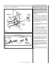
Figure 10
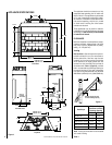
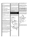
Step 4. Install the Vent System & Exterior
Termination -
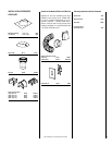
Slip a 10" (254 mm) B-Vent system over the
appliance collar (
Figure 10
) and secure
with four sheetmetal screws (# 8 or larger).
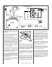
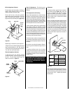
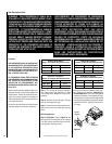
Minimum overall height of the vent system
and appliance must be 12' (3.66 m) vertical
(no offset) or 17' (5.18 m) when an offset up
to 45 degrees from the vertical is used. The
lower part of the offset must not begin less
than 3' (0.914 m) above the top of the
fireplace
(see Figure 11 )
.
Maximum overall height of the vent system and
appliance should not exceed 40 feet (12.19m).
Figure 11
Install the B-vent system in accordance with
the vent manufacturer's instructions.
CAUTION: THIS APPLIANCE CANNOT BE
VENTED HORIZONTALLY.
Note: Refer to the vent manufacturers installa-
tion instructions for variations of venting tech-
niques. If common venting of several units is
contemplated, it should be discussed with an
architect and the local Building Department.
Step 5. Field Wiring – Refer to Section A for
millivolt appliances and Section B for electronic
appliances.
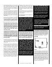
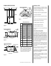
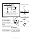
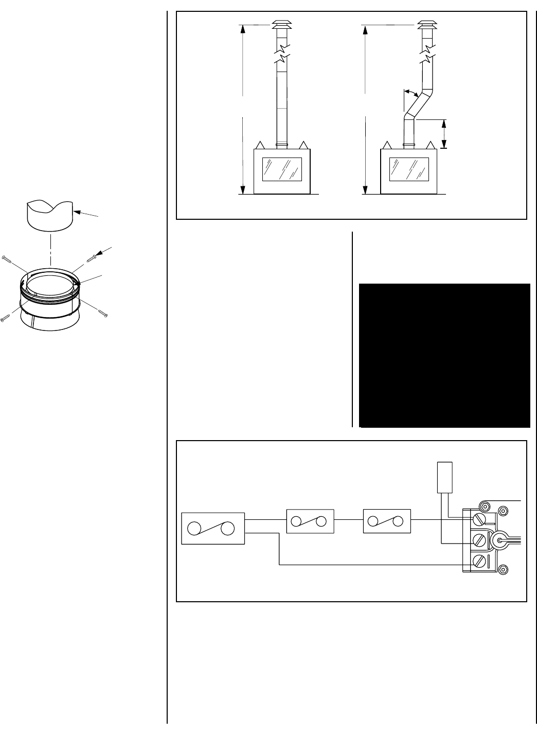
A. Millivolt Wiring – Units are fitted at the
factory with an SIT millivolt gas control valve.
The valve has been tested with and approved
for use with these appliances and is listed
accordingly. Refer to
Figure 12
for the wiring
diagram.
12 ft.
Minimum
17 ft.
Minimum
45 degrees
max.
3 ft.
Minimum
to Offset
The gas valve has been set in place and has been
pre-wired at the factory. Locate the wall switch
(not provided) or optional remote control in the
desired location and connect the millivolt wire
(see Figure 12 ).
CAUTION: DO NOT CONNECT THE WALL
SWITCH TO A 120V POWER SUPPLY.
Note: The ends of the 18' coiled wire must be
connected to the wall switch (not supplied) for
the appliance to operate.
B. Electronic Wiring – The electronic appli-
ance must be connected to the main power
supply. To install, route a 3-wire 120V 60Hz
power supply to the appliance junction box
and ground.
IMPORTANT: Ground lead must be con-
nected to the green screw located on
the outlet box. See
Figure 16
on page 9.
Failure to do so will result in a potential
safety hazard. The appliance must be
electrically grounded in accordance with
local codes or, in the absence of local
codes, the National Electrical Code,
ANSI/NFPA 70-(latest edition). (In
Canada, the current CSA C22-1 Cana-
dian Electrical Code.)
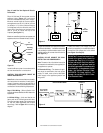
Figure 12
BLACK
BLACK
DAMPER SWITCH
LIMIT SWITCH
MILIVOLT WIRING DIAGRAM
TH
TP
TP
TH
THERMOPILE
WALL MOUNTED
ON/OFF SWITCH
GAS VALVE
BLACK
WHITE
10”
Type B-Vent
Flue Outlet
Collar
Securing
Screws
Locate and install a low voltage (24V) wall
switch (not supplied) in the desired location.
Connect the low voltage wire to this switch
(
see Figure 13
on Page 8)
.