


8
NOTE: DIAGRAMS & ILLUSTRATIONS NOT TO SCALE.
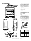
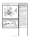
Figure 14
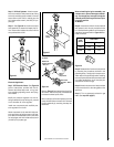
1. Route a 3-wire 120V 60Hz power supply line
to the appliance junction box wires and ground
(Figures 13 ).
2. After wiring is complete, replace the appli-
ance junction box cover and secure with the hex
head screws previously removed.
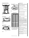
Step 6. Connecting Gas Line – Make gas line
connections. All codes require a shut-off
valve mounted in the supply line.
Figure 16
on page 9
illustrates the method for con-
necting the gas supply. The flex-line method
utilizing the gas flex line provided with the
appliance is acceptable in the U.S., how-
ever, Canadian requirements vary depend-
ing on locality. Installation must be in com-
pliance with local codes.
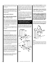
The gas control valve is located in the lower
control compartment. To access the valve
remove the refractory access panel and set
aside
(Figure 14 ).
The control valve has a
3/8" (10 mm) NPT thread inlet port.
Secure all joints tightly using appropriate
tools and sealing compounds (ensure pro-
pane resistant compounds are used in pro-
pane applications).
Turn on gas supply and test for gas leaks,
using a gas leak test solution (also referred to
as bubble leak solution).
Refractory
Access Panel
SIT Valve
Shown
Note: Using a soapy water solution (50% dish
soap, 50% water) is an effective leak test
solution but it is not recommended, because
the soap residue that is left on the pipes/
fittings can result in corrosion over time. Never
use an open flame to check for leaks.
A. Light the appliance (refer to the lighting
instructions label in the control compartment
or in the Homeowner's Care and Operation
Instructions).
B. Brush all joints and connections with the
gas leak test solution to check for leaks. If
bubbles are formed, or gas odor is detected,
turn the gas control knob to the “OFF” posi-
tion. Either tighten or refasten the leaking
connection and retest as described above.
C. When the gas lines are tested and leak free,
be sure to rinse off the leak testing solution.
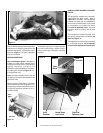
Step 7. Optional Outside Air Kits – Combus-
tion (outside make-up air) kits, Model FOAK-4
or FAOK-4LD, may used with these appli-
ances. Refer to the installation instructions
packaged with the air kits for specific installa-
tion information. The outside air kit must be
installed before the fireplace is framed and
enclosed in the finished wall.
Outside air drawn into the fireplace supplies
air to the fire for combustion. Only one com-
bustion air duct on the right side of the fire-
place is necessary if installed.
If additional length of duct is necessary, pur-
chase locally available U.L. Class 0 or Class 1
metallic ducting. The duct may extend up to
50' (15.24 m) in any direction.
There is one hand operated air gate shut-off,
for utside make-up air, located at the right side
of the fireplace opening behind the screen. To
open, lift and pull the handle out. The combus-
tion air damper should be
open when the
fireplace is in use
and, to prevent outside air
from entering your home, fully closed when
the fireplace is not in operation.
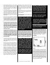
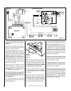
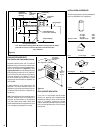
WHITE
DAMPER SWITCH
LIMIT SWITCH
CONNECTOR
BLACK
BLACK
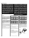
ELECTRONIC WIRING DIAGRAM
BK
W
24 V.
TRANSF
120 V.
ELECTRONIC IGNITION
CONTROL BOARD
WALL MOUNTED
ON/OFF SWITCH
PILOT BURNER
IGNITER-SENSOR
ASSEMBLY
GAS VALVE
EV2
EV1
GROUND
CONNECTOR
GREEN LED
WHITE
ORANGE
BLACK
PURPLE
GREEN
BLUE
BLACK
WHITE
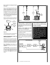
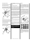
Junction Box
White
Green
Red
Black
Neutral
Side of
Receptacle
Green
Ground
Screw
Hot
Side of
Receptacle
Ta b
Broken
Plug blower
into this
receptacle
Tab Intact
120 VAC - Black
n
e
e
r
G-dn
u
o
r
G
e
ti
h
W
-
lar
t
u
e
N
Figure 13