


7
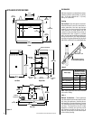
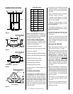
NOTE: DIAGRAMS & ILLUSTRATIONS NOT TO SCALE.
Figure 11
Step 5. Field Wiring – Refer to Section A for
millivolt appliances and Section B for electronic
appliances.
A. Millivolt Wiring – The gas valve has been set
in place and has been pre-wired at the factory.
No additional wiring is required unless the
optional wall switch or optional remote control
kit is to be installed. Locate the optional wall
switch or optional remote control in the desired
location and connect the millivolt wire
(see
Figure 11 )
.
CAUTION: DO NOT CONNECT THE WALL
SWITCH TO A 120V POWER SUPPLY.
Note: Optional wall switch not supplied. If the
optional wall switch is not installed, the ends of
the 15' coiled wire must be connected with a wire
nut (not supplied) for the appliance to operate.
Figure 12
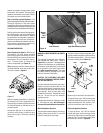
Step 6. Connecting Gas Line – Make gas line
connections. All codes require a shut-off valve
mounted in the supply line.
Figure 15
illus-
trates two methods for connecting the gas
supply. The flex-line method is acceptable in
the U.S., however, Canadian requirements vary
depending on locality. Installation must be in
compliance with local codes. The gas control
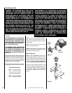
valve is located in the lower control compart-
ment. To access the valve remove the refrac-
tory access panel and set aside
(Figure 13 )
.
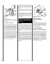
B. Electronic Wiring – The electronic appli-
ance must be connected to the main power
supply. To install:
1. Route a 3-wire 120V 60Hz power supply to
the appliance junction box and ground.
(See
Figures 12 and 14 ).
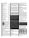
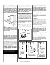
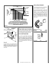
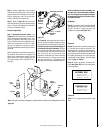
SIT Millivolt Wiring Diagram
*
For Wall Switch Attachment Only.
If any of the original wire as supplied must be replaced, it
must be replaced with Type AWM 105°C – 18 GA. wire.
Thermopile
TH
TP
TH
TP
Limit Switch
*
Damper
Switch
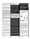
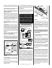
1. If any of the original wire as supplied must be replaced,
it must be replaced with Type AWM 200°C – 18 GA.
wire.
2. 120V, 60Hz – Less than 3 amps.
BK
Junction Box
Transf.
120 V.
24 V
Factory Wired Field Wired
BL
Electronic Wiring Diagram (Honeywell)
(Optional ON/OFF Switch Wiring)
R
BK
BL
To Opposite Side
OPT
FAN
G
W
OPT. ACCESSORY
SWITCH
120
VAC.
BK
LIMIT
SWITCH
W
Gas Valve
B
OPTIONAL
ON/OFF SWITCH
OR WALL SWITCH
R
IGNITER
CONTROL
PILOT
ASSEMBLY
Break
Off Tab
DAMPER
SWITCH
BK
BK
WHT
BK
BK
G
G
IMPORTANT: Ground lead must be connected
to the green screw located on the outlet box.
See
Figure 12
. Failure to do so will result in
a potential safety hazard. The appliance
must be electrically grounded in accordance
with local codes or, in the absence of local
codes, the National Electrical Code, ANSI/
NFPA 70-(latest edition). (In Canada, the
current CSA C22-1 Canadian Electrical Code.)
The millivolt control valve has a ³⁄₈"
(10 mm) NPT thread inlet port. The electronic
control valve has a ¹⁄₂" (13 mm) NPT thread
inlet port and is fitted with a ¹⁄₂" x ³⁄₈" (13 mm
x 10 mm) NPT fitting. Both the millivolt and
electronic models are fitted with a 3" (76 mm)
long nipple, ³⁄₈" NPT. Plan the connections
accordingly.
Secure all joints tightly using appropriate
tools and sealing compounds (ensure pro-
pane resistant compounds are used in pro-
pane applications).
Turn on gas supply and test for gas leaks,
using a gas leak test solution (also referred to
as bubble leak solution).
Note: Using a soapy water solution (50% dish
soap, 50% water) is an effective leak test
solution but it is not recommended, because
the soap residue that is left on the pipes/
fittings can result in corrosion over time. Never
use an open flame to check for leaks.
A. Light the appliance (refer to the lighting
instructions label in the control compartment
or in the Homeowner's Care and Operation
Instructions).
B. Brush all joints and connections with the
gas leak test solution to check for leaks. If
bubbles are formed, or gas odor is detected,
turn the gas control knob to the “OFF” posi-
tion. Either tighten or refasten the leaking
connection and retest as described above.
C. When the gas lines are tested and leak free,
be sure to rinse off the leak testing solution.
D. When the gas lines are tested and leak free,
observe the individual tongues of flame on the
burner. Make sure all ports are open and
producing flame evenly across the burner. If
any ports are blocked, or partially blocked,
clean out the ports.
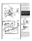
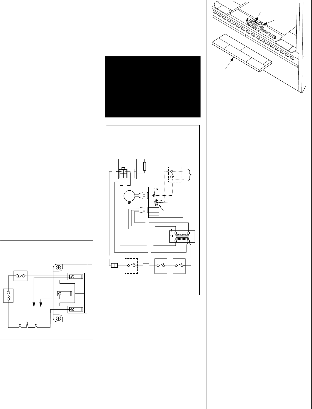
Figure 13
Refractory
Access Panel
SIT Valve Shown
Gas Controls
on Valve
Piezo
Ignitor
2. Locate and install a low voltage (24V) wall
switch (not supplied) in the desired location.
Connect the low voltage wire to this switch
(see
Figure 12 )
.
3. After wiring is complete, replace the appli-
ance junction box cover and secure with the
hex head screws previously removed.
Maximum overall height of the vent system and
appliance should not exceed 40 feet (12.19 m).
Install the B-vent system in accordance with
the vent manufacturer's instructions.
CAUTION: THIS APPLIANCE CANNOT BE
VENTED HORIZONTALLY.
Note: Refer to the vent manufacturers installa-
tion instructions for variations of venting tech-
niques. If common venting of several units is
contemplated, it should be discussed with an
architect and the local Building Department.
Install the B-vent system in accordance with
the vent manufacturer's instructions.