


10
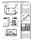
NOTE: DIAGRAMS & ILLUSTRATIONS ARE NOT TO SCALE.
LENNOX MERIT
®
SERIES B-VENT GAS FIREPLACES • 36" LMBV MODELS • INSTALLATION INSTRUCTIONS
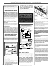
Electronic Appliance Checkout
To light the burner, turn ‘ON’ the optional remote
wall switch and turn the gas control switch to
the “ON” position. Ensure the ignitor lights the
pilot. The pilot ame should engulf the ame
rod as shown in Figure 20.
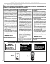
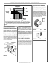
Figure 19: Millivolt Pilot
3/8” Min
(9 mm)
Hood
Pilot
Nozzels
Ignitor Rod
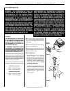
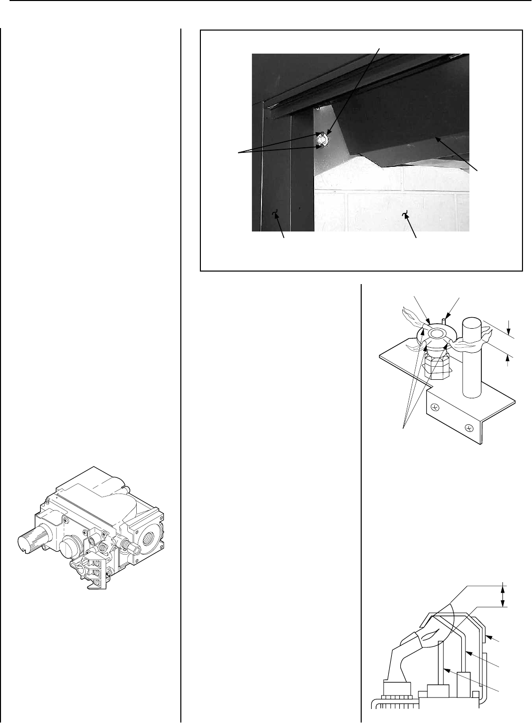
Manual Limit Switch
(manually-reset blocked flue safety switch)
This appliance is equipped with a manually-reset
blocked ue safety switch. Refer to Figure 18
for its location. If during appliance operation,
the ame goes out (independently of the burner
on/off wall switch), it may be due to the opera-
tion of this safety limit switch. First allow the
appliance to cool. Then reset the safety switch
by pushing the red reset button on the back of
the switch.
CAUTION: THE ELECTRONIC APPLIANCE
SHOULD BE TURNED OFF BEFORE
REMOVING THE LIMIT SWITCH.
To access the safety limit switch reset button,
remove the two screws. Pull out limit switch
with low voltage wires attached, push the reset
button, then reinstall the limit switch. At this
time turn the electronic appliance back on.
The appliance should then relight and remain
lit. If this does not occur, turn off the appli-
ance and call a qualified service technician.
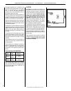
Millivolt Appliance Checkout
The pilot ame should be steady, not lifting
or oating. Flame should be blue in color with
traces of orange at the outer edge.
The top 3/8" (9 mm) at the pilot generator
(thermopile) should be engulfed in the pilot
ame. The ame should project 1" (25 mm)
beyond the hood at all three ports (Figure 19 ).
Replace logs if removed for pilot inspection.
To light the burner; turn “ON” the remote wall
switch and rotate the gas valve control knob
counterclockwise to the “ON” position (“ON”
will be to the left hand side of the valve).
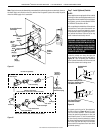
Figure 18
Limit
Switch
Screws
Manual Reset Limit Switch
Lintel
Extention
Fireplace Front Left Side Refractory Panel
Figure 17
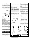
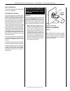
Operate the actuator through several cycles
including the "lock" position. Ensuring proper
operation and freedom of movement. Return
the actuator arm to the locked position.
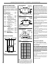
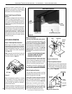
Step 8. Install Logs and Glowing
Embers
The logs are packaged and boxed within the
firebox. The bag of glowing embers is in the
lower control compartment. Remove the glow-
ing embers from the packaging and tear into
quarter size pieces (see the Care and Operation
Instructions).
Carefully position the ceramic fiber log assembly
onto the burner, refer to the Care and Opera-
tion Instructions for detailed log description
and placement instructions. Position the logs
onto the pins of the burner, with the cutouts
fitted around the burner tube. Ensure the rear
log matches the cutout on its bottom with the
position of the pilot.
APPLIANCE OPERATION
Step 9. Check Appliance Operation
With the gas line installed, run initial system
checkout before closing up the front of the unit.
Follow the pilot lighting instructions provided in
the Care and Operation Instructions. The piezo
ignitor is located in the control compartment
(see Figure 13 ).
Note: Instructions are also found on the pull
out labels attached to the gas control valve.
The valve is shown in Figure 17.
When first lighting the appliance, it will take
a few minutes for the line to purge itself of
air. Once purging is complete, the pilot and
burner will light and operate as indicated in
the instruction manual.
Subsequent lightings of the appliance will not
require such purging. Inspect the pilot ame
(remove logs, if necessary, handling carefully).
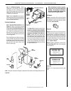
SIT Valve
Figure 20: Electronic Pilot
Proper Flame
Adjustment
Hot Surface
Igniter
Flame Rod
Ground
Electrode
3/8 To 1/2 Inch
(9 mm to 13 mm)