


NOTE: DIAGRAMS & ILLUSTRATIONS NOT TO SCALE.
12
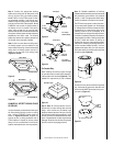
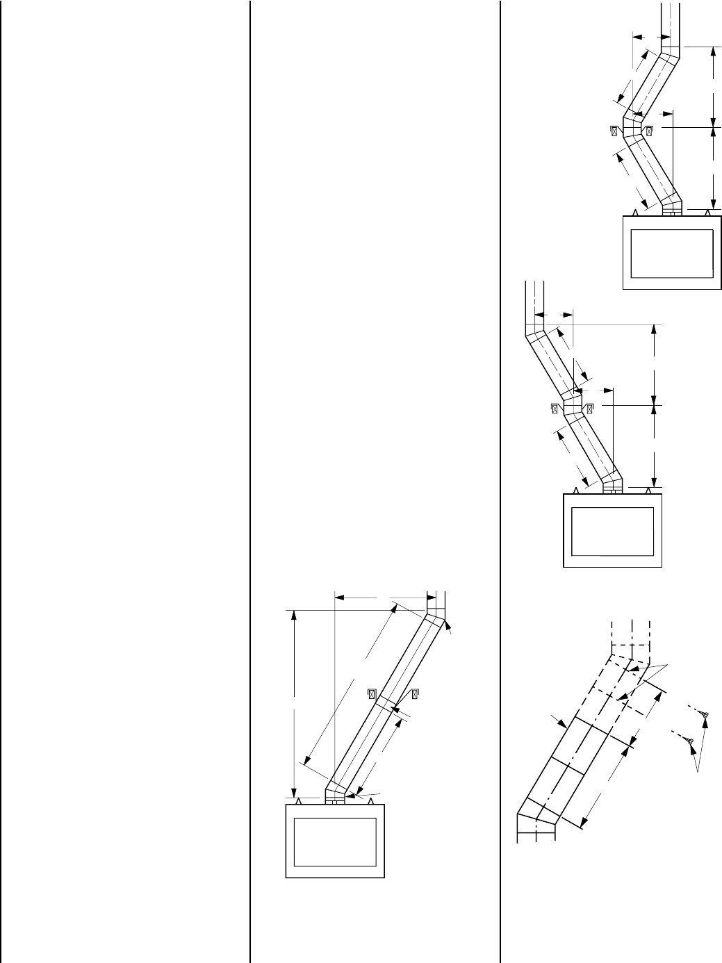
Figure 38
A
1
C
1
B
1
B
2
C
2
A
2
A
1
C
1
B
1
B
2
C
2
A
2
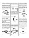
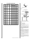
Figure 39
Chimney
Section
Joints
No. 8 x 1/2" SMS
Screws Required At
Every Joint Past 6'
No Screws Required In
Joints For First 6' of Offset
4'
6'
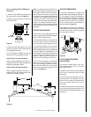
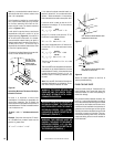
A 1/8" diameter hole must be drilled in the
chimney joint using a 1/8" diameter drill. Hole
should be drilled in center of joint overlap (
see
Figure 40
). Be sure to drill only through the
outer chimney casting. Do not puncture the
inner flue.
Maximum offset of chimney system is 30°.
Two offsets must not be assembled to form a
60° offset. However, two sets of offset and
return elbows may be used on a single flue
system, provided the total height of the sys-
tem exceeds 25'.
Return elbow support straps must be securely
attached under tension (in shear) to structural
framing members above. Do not substitute a
FTF10-30 offset elbow in place of a FTF10-E30
return elbow.
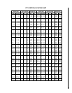
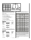
OFFSET CALCULATIONS
Step 1. Use Offset Chart to determine amount
of horizontal offset (A) and height (B) for
various chimney section assemblies.
Step 2. Use “Height of Chimney Only” column
in The Vertical Elevation Chart to determine
combinations of chimney used above return
elbow to achieve desired heights. Reference
Components Effective Height Chart in vertical
elevation chart section on page 13.
Step 3. Use Elevation Chart as job estimator
only. Add necessary firestop spacers and sta-
bilizers as required. Firestop spacers must be
used as shown in
Figures 23 and 24
and
stabilizers as shown in
Figure 29
.
3. The effective heights of the components are:
The Fireplace = 48-3/8"
FTF10-12 = 10-1/4"
FTF10-18 = 16-1/4"
FTF10-36 = 34-1/4"
FTF10-CTDTM Termination = 13"
FTF10-CT1 Termination = 12" to 18"
FTF10-CT2 Termination = 15" to 23"
FTF10-S4 Stabilizer * = 3"*
* Required for every 30' of vertical chimney
and/or 10' of offset chimney.
4. Determine amount of chimney height re-
quired by subtracting total combined height of
all pre-selected components (fireplace and
chimney components from total desired height.)
Reference Vertical Elevation Chart and deter-
mine the number of chimney sections (quantity
and length) required.
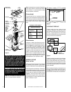
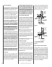
SPECIAL OFFSET INSTRUCTIONS
To clear any overhead obstructions, you may
offset your chimney system using Security's
30° offset and return elbows. Use two elbows -
an offset elbow to initiate the offset and a return
elbow to terminate it. A 30° offset elbow, an-
gling in any direction, may be the first compo-
nent used off the top of the fireplace flue collar.
The offset and return elbows may be attached
together, or a section or sections of chimney
may be used between, but do not exceed 20' in
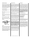
total length between elbows. If sections of
pipe exceed 10' between elbows, a chimney
stabilizer must be used at the midpoint (
Figure
37
). The stabilizer support straps must be
attached under tension (in shear) to structural
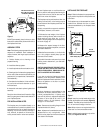
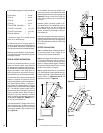
framing members above. When two sets of
elbows are used, the maximum combined
length of chimney used between elbows can-
not exceed 20' (
Figure 38
). Example: If C
1
=
10' then C
2
cannot exceed 10'.
If an offset exceeds 6' in length, each chimney
joint beyond the first 6' of offset to the return
elbow, must be secured by a No. 8 x 1/2" sheet
metal screw located at the underside of the
joint (
Figure 39
).
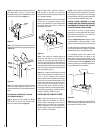
Figure 37
Stabilizer
A
1
20'
Max.
B
1
10' Max.
Offset
Elbow
Return
Elbow