


NOTE: DIAGRAMS & ILLUSTRATIONS NOT TO SCALE.
8
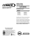
Figure 17
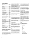
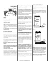
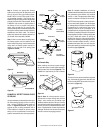
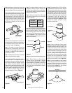
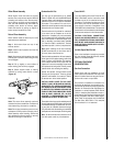
Step 5. The fireplace should be secured to the
side framing members through the nailing flange
(
Figure 18
).
Figure 18
Note: The nailing flange and the area directly
behind the nailing flange is exempt from the
clearances described on the fireplace clearance
label.
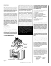
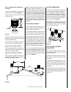
For Canadian Installations, Proceed
with Steps 6 through 9
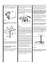
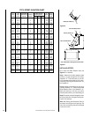
Step 6. Attach the cold climate kit, Model
FTF10-CCK1-LD, around the chimney collar
with the screws provided (
Figure 19
).
Step 4. The fireplace should be anchored to the
floor. Bend down the four (4) anchor tabs
located at the base of the fireplace and secure
to the floor with 8d nails (
Figure 17
).
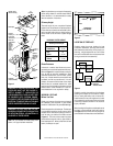
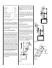
Figure 20
Note: The optional collar duct kit, Model FTF10-
CDK, should be installed after the chimney has
been attached to the flue collar.
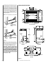
Step 2. Using standard construction framing
techniques, construct openings for the chim-
ney through the ceiling(s) and roof or through
an outside chase. All framing must maintain the
minimum air space clearance at all times.
CAUTION: ALLOW A MINIMUM 2" (51 MM)
CHIMNEY AIR SPACE TO COMBUSTIBLE FRAM-
ING MEMBERS THROUGHOUT VERTICAL AND/
OR OFFSET CHIMNEY INSTALLATIONS.
A minimum 2" (51 mm) air space must be
reserved for all combustible and noncombus-
tible materials extending for any continuous
length surrounding the chimney.
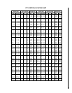
Reference
Figures 15 and 16
and charts “Fram-
ing Dimensions for Ceiling and Roof,” which
specify minimum ceiling and roof dimensions.
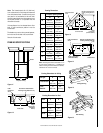
For new construction, to determine chimney cen-
ter line, use plumb line from ceiling or roof above
fireplace to the center of fireplace flue collar.
For remodeling, plumb to the center of the
fireplace flue collar from the ceiling or roof
above. Drive a nail through the ceiling or roof
from below to mark position. Mark and cut a hole
in the ceiling (around the nail) (
Figure 20
). Then
plumb from ceiling or roof directly above the cut
hole to determine roof hole position.
Step 7. Connect the 4" (102 mm) Class 0 air
duct provided, to the collar on the chimney
collar enclosure with the screws provided in the
kit’s hardware package.
Step 8. Route the Class 0 air duct out the back
or side wall, up through the ceiling or floor
joists to an outside wall. The duct inlet should
be located above snow level or above any
anticipated snow level.
Figure 19
Note: If the fireplace is installed against an
inside wall, the Class 0 air duct may be ex-
tended into a ventilated attic space at least 18"
(457 mm) above the attic floor. Secure the duct
hood to a vertical post with the inlet positioned
downward. Ensure that nothing blocks the hood
opening. This duct must never terminate higher
than the fireplace chimney.
Step 9. Cut or frame a hole through the outside
wall for the installation of the duct inlet hood. A
4-1/2" (114 mm) diameter hole is required.
Feed the loose end of the flexible duct through
the hole cut for the inlet hood and attach to the
collar on the inlet hood using (2) two screws.
Insert the hood into the opening. Secure in
place with nails driven through the holes in
hood flange. Seal with noncombustible water-
proof silicon type caulking. If additional duct is
needed, use Class 0 metallic air duct.
INSTALLING THE CHIMNEY SYSTEM
Step 1. Check the flue damper for proper op-
eration. When the flue damper is in the fully
closed position, the damper control lever is
pushed all the way to the rear of the firebox.
When the damper is in the fully open position,
the flue damper control lever is pulled all the
way to the front of the firebox.
8d Nail
Framing
Stud
Nailing
Flange
Enclosure Box
Anchor
Ta b