


NOTE: DIAGRAMS & ILLUSTRATIONS NOT TO SCALE.
16
Vent Free Appliances
These units have been tested and approved to
ANSI/IAS/AGA Z21.11.2 for use with unvented
gas appliances and complies with the stan-
dard for Factory-Built fireplaces, UL 127.
The unit has been tested for use with any
unvented gas log sets having a maximum rating
of 40,000 BTU. The minimum mantle configu-
rations are outlined in
Figures 43 and 44
.
These fireplaces have been marked with a
maximum rating of 40,000 BTU to assure that
homeowners do not exceed the allowable lim-
its for all allowed installations of mantles.
NEVER INSTALL AN UNVENTED GAS LOG
SET WITH A BTU GREATER THAN 40,000.
CAUTION: WHEN USING THE DECORATIVE
GAS APPLIANCE, THE FIREPLACE DAMPER
MUST BE SET IN THE FULLY OPEN POSITION.
CAUTION: PLUMBING CONNECTIONS SHOULD
ONLY BE PERFORMED BY A QUALIFIED, LI-
CENSED PLUMBER. MAIN GAS SUPPLY MUST
BE OFF WHEN PLUMBING GAS LINE TO FIRE-
PLACE OR PERFORMING SERVICE.
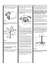
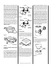
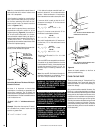
If you’re installing a gas line, connect it before
the fireplace is framed and enclosed in the
finished wall. The gas knockout is determined
by the indentation located at the bottom and
slightly off center in the side refractories. THE
KNOCKOUT IS ALWAYS REMOVED FROM IN-
SIDE THE FIREPLACE. DO NOT REMOVE THE
KNOCKOUT UNLESS YOU ARE INSTALLING A
GAS LINE. If removal is attempted from the
outer wrapper, side refractory damage may
occur. With a medium-sized hammer, lightly
tap the surface of the indentation. The refrac-
tory material is very thin in this area and is easily
removed. Once a small hole has been made,
continue tapping until you have reached suffi-
cient diameter for the gas line to fit through. The
entire knockout does not have to be removed.
Remove insulation in the gas line channel.
IMPORTANT: REPACK INSULATION MATERIAL
IN SQUARE HOLE AROUND GAS LINE, INTE-
RIOR AND EXTERIOR OF FIREPLACE, TO SEAL.
Glass Doors
If glass doors are to be installed on these
fireplaces, refer to specific installation instruc-
tions packed with the glass doors. Use only the
doors that are listed for use with these fire-
places. Use of other non-listed glass door on
these fireplaces may constitute a potential fire
hazard and is not recommended.
CAUTION: CERTAIN GLASS DOORS OVER-
LAP THE BLACK METAL FACING OF THE FIRE-
PLACE. IF THE FIREPLACE HAS BEEN FACED
WITH NONCOMBUSTIBLE MATERIALS,
THERE MIGHT NOT BE SUFFICIENT CLEAR-
ANCE TO INSTALL THE GLASS DOORS OF
YOUR CHOICE. ENSURE ADEQUATE CLEAR-
ANCE IS MAINTAINED AT ALL TIMES SO AS
NOT TO INTERFERE WITH THE INSTALLA-
TION AND OPERATION OF GLASS DOORS.
COLD CLIMATE INSULATION
If you live in a cold climate, it is especially
important to seal all cracks around the fire-
place opening with noncombustible material
and wherever cold air could enter the room.
Surrounding materials must be caulked where
it meets the black metal facing of the fireplace
to avoid cold air intrusion. Use noncombus-
tible caulking material only on fireplace facing
to seal. Also, the outside air inlet duct should
be wrapped with noncombustible insulation to
minimize the formation of condensation. Do
not place insulation materials on top of fire-
place or against chimney sections.
Note: A 2" air space must be preserved for all
combustible materials extending for any con-
tinuous length adjacent to the chimney.
It is especially important to insulate between
the studs of an outside chase cavity and under
the floor if the floor is above ground level. Do
not place insulation directly against the fire-
place or chimney system.
The installation of the CCK1 is recommended.
Refer to Steps 6 thru 9 on Page 8.
FIREPLACE FINISHES
It is sometimes best to frame your fireplace
after it is positioned and the chimney is in-
stalled. Frame enclosure for chimney and fire-
place with 2 x 4’s (or heavier) lumber.
Note: The header may rest on the two (2) metal
top spacers on top of the unit but the header
must not be notched to fit around the spacers.
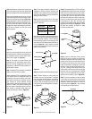
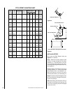
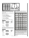
Mantels and Trim
These fireplaces may sit directly on a combus-
tible surface. A 2" air space is required between
combustible framing and the chimney. In
Canada, the minimum height for a combustible
mantel is 18" (457 mm) above the fireplace
opening.
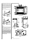
Figure 43
shows typical Canadian
installations. For installations other than Canada,
combustible mantels and trim may either project
in front or be flush with the finished wall as per
NFPA 211 section 7-2.3.3. and
Figure 44
.
Figure 43
Figure 44
Finished
Wall
Header
8" Max.
(203mm)
Noncombustible
Wall Covering
Fireplace Opening
Canadian Installation
18" Min.
(457mm)
Combustible
Mantel
Spacer
Finished
Wall
Header
Noncombustible
Wall Covering
Fireplace Opening
U.S. Installation
12"
Min.
Combustible
Mantel
Spacer
*
A 1-1/2” Projection Is Permitted
Between The Face Top And Mantle
*
12"
Max.
If a mantel is of a noncombustible material, it
is exempt from these requirements as long as
it does not interfere with the installation or
operation of glass doors, or block the air
circulating opening of the fireplace
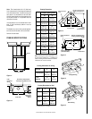
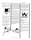
Hearth Extensions and Wall Shields
A hearth extension must be installed with
all fireplaces. It is to protect the combustible
floor in front of the fireplace from both radiant
heat and sparks. The hearth extension must
extend 12" beyond both sides of the fireplace
opening and 20" beyond the front (
see Figure
45 )
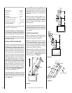
. Use a hearth extension constructed of a
durable noncombustible material having an
equal or better (lower k value) insulating value
of k = .84 BTU IN/FT
2
HR °F or a thermal
resistance that equals or exceeds r = 1.19 HR
°F FT
2
/BTU IN. With these values, determine
the minimum thickness/material required us-
ing the formula and
Page 17
.