


NOTE: DIAGRAMS & ILLUSTRATIONS NOT TO SCALE.
10
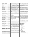
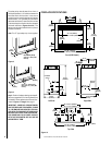
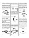
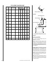
Locking Band
Waterproof
Caulk
Figure 32
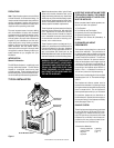
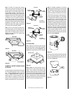
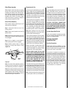
Step 9. Security Chimneys locking bands,
Model FLB, may be required if the chimney
extends too high above the roof flashing. As a
general rule, if the chimney extends more than
6' above the roof flashing, the use of locking
bands is advisable to strengthen the chimney
assembly. Align the locking band at the chim-
ney joint. Locking bands wrap around pipe
joints equally covering the joints of both pipe
sections. Use the nut provided and TIGHTEN
snugly. Do not overtighten as this might dam-
age the chimney section (
refer to Figure 29
).
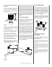
Note: If chimney extends more than 8' above
roof surface, guy wires are also recommended.
Use three (3) guy wires, attach to locking band
assembly, extend and secure to roof in a
triangular pattern (Figure 33 ). Guy wires are
not supplied by the manufacturer.
Roof Ridge
120°
Step 8. The standard Security FTF10 roof flash-
ing assemblies include a storm collar. Slide the
storm collar over outer chimney, rest on flash-
ing spacers and align with top surface of flash-
ing. Insert tab in slot, pull tight and bend tab
back over slot. Seal storm collar to outer chim-
ney with roof caulking or mastic around entire
circumference of pipe. Also add extra roof
caulking to the tab/slot area to seal completely
against water penetration (
Figure 32
). Check
all joints very carefully to ensure no water
intrusion can take place.
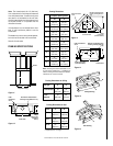
Figure 33
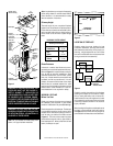
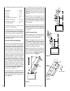
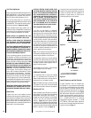
1" Min. Air Space
To Combustibles
FTF8-S4 Stabilizer
Figure 28
Security's chimney sections do not need to be
screwed together. Additional reinforcement is
not necessary except in certain offset condi-
tions (refer to page 12,
Figure 39
).
Step 5. The height of vertical chimney pipe
supported only by the fireplace must not ex-
ceed 30'. Chimney heights above 30' must be
supported by a Model FTF10-S4 stabilizer in-
stalled at 30' intervals.
Note: The Model FTF10-S4 adds 3" net effective
height to the total chimney system.
Install the Model FTF10-S4 stabilizer by fitting
inner section down into respective section of
proceeding flue pipe and locking outer stabi-
lizer section into place over the outer chimney
pipe. Position for proper clearance through
framed opening and nail straps securely (under
tension in “shear”) into place on framing. Use
8d nails. Attach successive lengths of chimney
pipe directly to stabilizer using same tech-
niques as described in Step 4 (
Figure 29
).
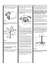
Figure 29
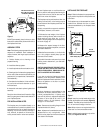
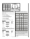
Figure 31
Next, slide roof flashing over extended chimney
section that previously has been installed above
the roof opening in Step 4. FTF10 flashings
require flashing spacers. Slide flashing all the
way down until the flashing base rests flat on
the roof (
Figure 30
). Again, check the vertical
position of the chimney and the 2" minimum air
space to combustibles.
Figure 30
Note: Do not caulk or seal the ventilating openings.
Step 7. Secure flashing by nailing along the
perimeter into roof using 8d nails. If shingled
roof, slide upper end and sides of roof flashing
under shingles (trim if necessary), seal the top
and both sides of the flashing to the roof with
roof caulking. Cover nail heads with roof caulk-
ing (
Figure 31
).
FTF10 Chimney
FTF10 Flashing
Flashing Spacers
Do Not Seal
Note: Do not apply excessive pressure to any
subsequent chimney sections following the
stabilizer when installing. Ensure each subse-
quent chimney section is securely attached by
testing as noted in Step 4.
Step 6. Select the proper Security Chimneys
roof flashing based on pitch of roof. Use chart
below for selection:
Roof Pitch Model
Flat to 6/12 F10F6
6/12 to 12/12 F10F12
Note: Assemble one component of chimney at a
time (inner section first; then outer section last)
before preceding with the next complete section.
Continue to assemble the chimney up through
framed opening. Assemble just enough to pen-
etrate the roof flashing openings (
Figure 28
).
Always maintain 2" minimum air space to com-
bustible materials and always check each chim-
ney joint (inner and outer) to ensure proper
engagement. Check vertical alignment of chim-
ney so that it projects from the roof in true
vertical position.