


NOTE: DIAGRAMS & ILLUSTRATIONS NOT TO SCALE.
7
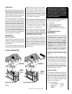
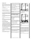
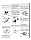
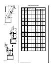
FRAMING SPECIFICATIONS
Figure 11
Figure 12
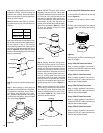
Figure 13
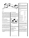
Figure 15
Figure 16
Figure 14
A
B
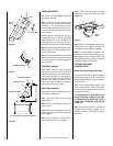
Ceiling Framing
C
D
Roof Framing
Header
Fireplace Framing
B
A
A
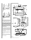
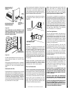
Outside Chase
G
H
Back Wall of Chase/Enclosure
Including Finising Materials
if any
Rough
Framing Face
(Unfinished Shown)
FOAK
Combustion
Air Kit - Optional
Corner Installation
J
D
A
E
F
Back Wall of
Chase/Enclosure
Including Finising
Materials
if any
Rough
Framing Face
(Unfinished Shown)
FOAK Combustion
Air Kit - Optional
C
A
G
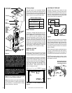
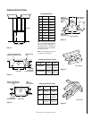
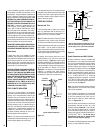
Inside Chase
Back Wall of Chase/Enclosure
Including Finising Materials if any
Rough
Framing Face
(Unfinished Shown)
FOAK Combustion
Air Kit
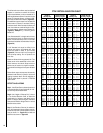
Framing Dimensions
A 49" 1245 mm
B 46-1/2" 1181 mm
C 33" 838 mm
D 17-1/2" 445 mm
E 81" 2057 mm
F 40-3/8" 1026 mm
G 24" 607 mm
H 23" 584 mm
J 57-1/4" 1454 mm
Framing Dimensions for Roof
Pitch C D*
0/12 16-1/2" 16-1/2"
(419 mm) (419 mm)
6/12 16-1/2" 19"
(419 mm) (483 mm)
12/12 16-1/2" 23-1/2"
(419 mm) (597 mm)
Framing Dimensions for Ceiling
Flue Type A B
FTF8 Vertical 16-1/2" 16-1/2"
(419 mm) (419 mm)
FTF8 Offset 30° 16-1/2" 27"
(419 mm) (686 mm)
* Perpendicular to roof ridge
Note: All framing dimensions calcu-
lated for 5/8" nailing flange depth and
1/2" dry wall at the fireplace face. If
sheathing the chase or finishing with
other thickness materials, calculations
will need to be made.
Note: A, C and G dimensions include
1" clearance to combustibles.