


3
NOTE: DIAGRAMS & ILLUSTRATIONS NOT TO SCALE.
Carbon Monoxide Poisoning: Early signs of
carbon monoxide poisoning are similar to the
flu with headaches, dizziness and/or nausea. If
you have these signs, obtain fresh air immedi-
ately. Turn off the gas supply to the appliance
and have it serviced by a qualified profes-
sional, as it may not be operating correctly.
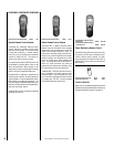
To open the control compartment access panel,
actuate the spring-loaded magnetic catches
securing the panel. First, depress the outer top
right corner of the panel until the catch "pops"
the door free. Then, gently pull the door forward
until the left top corner "pops" free, allowing the
panel to swing out and down to open.
On millivolt systems, the piezo ignitor, Hi/Lo
flame adjustment knob, and pilot and main gas
ON/OFF control knob are located on the mod-
esty panel.
On both millivolt and electronic systems the
gas valve is located behind the modesty panel.
See
Figure 1.
OPERATION AND CARE OF YOUR
APPLIANCE
Appliance operation may be controlled by the
following means: the factory provided modesty
panel-mounted ON-OFF control switch, an op-
tional wall-mounted ON-OFF switch or optional
remote control.
The modesty panel mounted ON-OFF control
switch is located behind the control compart-
ment access panel, below the appliance front
glass enclosure panel. See
Figure 1.
Gas Controls/Control Compartment
Access
The gas controls can be found behind the
control compartment access panel.
Maximum manifold pressure is 3.5 in. w.c.
(0.87 kPa) for natural gas and 10 in. w.c.
(2.49 kPa) for LP/Propane gas.
Do not use these appliances if any part has
been under water. Immediately call a qualified,
professional service technician to inspect the
appliance and to replace any parts of the
control system and any gas control which
have been under water.
Ne pas se servir de cet appareil s'il a été plongé
dans l'eau, complètement ou en partie. Appeler
un technicien qualifié pour inspecter l'appareil et
remplacer toute partie du système de contrôle et
toute commande qui ont été plongés dans l'leau.
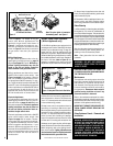
Test gage connections are provided on the
front of the millivolt gas control valve (identi-
fied OUT for the manifold side and IN for inlet
pressure. A ¹⁄₈" NPT test gage connection is
provided on the electronic gas control valve
adjacent to the outlet to the main burner.
Minimum inlet gas pressure to these appliances
is 5.0 inches water column (1.24 kPa) for natural
gas and 11 inches water column (2.74 kPa) for
propane for the purpose of input adjustment.
Maximum inlet gas supply pressure to these
appliances is 10.5 inches water column (2.61
kPa) for natural gas and 13.0 inches water
column (3.23 kPa) for propane.
The appliance must be isolated from the gas
supply piping system (by closing its individual
manual shut-off valve) during any pressure test-
ing of the gas supply piping system at test
pressures equal to or less than ¹⁄₂ psig (3.5 kPa).
The appliance and its individual shut-off valve
must be disconnected from the gas supply
piping system during any pressure testing of
that system at pressures in excess of ¹⁄₂ psig
(3.5 kPa).
These appliances must not be connected to a
chimney or flue serving a separate solid fuel
burning appliance.
Any safety guard or screen removed for ser-
vicing the appliance must be replaced prior
to operating the appliance.
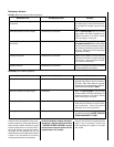
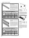
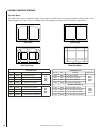
The following table shows the units' orifice size
for the elevations indicated.
ledoM
.oN
ezisecifirO
noitavelE
teeF
)sretem(
.taN.porP
TSVDE
FPVDE
RCVDE
LCVDE
"521.094#
0054-0
)2731-0(
WARNING: FAILURE TO COMPLY WITH
THE INSTALLATION AND OPERATING IN-
STRUCTIONS PROVIDED IN THIS DOCU-
MENT WILL RESULT IN AN IMPROP-
ERLY INSTALLED AND OPERATING AP-
PLIANCE, VOIDING ITS WARRANTY. ANY
CHANGE TO THIS APPLIANCE AND/OR
ITS OPERATING CONTROLS IS DANGER-
OUS. IMPROPER INSTALLATION OR USE
OF THIS APPLIANCE CAN CAUSE SERI-
OUS INJURY OR DEATH FROM FIRE,
BURNS, EXPLOSION OR CARBON MON-
OXIDE POISONING.
WARNING: CHILDREN AND ADULTS
SHOULD BE ALERTED TO THE HAZARDS
OF HIGH SURFACE TEMPERATURES. USE
CAUTION AROUND THE APPLIANCE TO
AVOID BURNS OR CLOTHING IGNITION.
YOUNG CHILDREN SHOULD BE CARE-
FULLY SUPERVISED WHEN THEY ARE IN
THE SAME ROOM AS THE APPLIANCE.
WARNING: DO NOT PLACE CLOTHING
OR OTHER FLAMMABLE MATERIALS ON
OR NEAR THIS APPLIANCE.
AVERTISSEMENT: SURVEILLER LES
ENFANTS. GARDER LES VÊTEMENTS,
LES MEUBLES, L'ESSENCE OU AUTRES
LIQUIDES À VAPEUR INFLAMMABLES
LOIN DE L'APPAREIL.
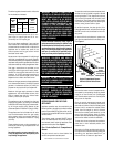
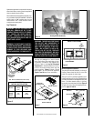
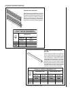
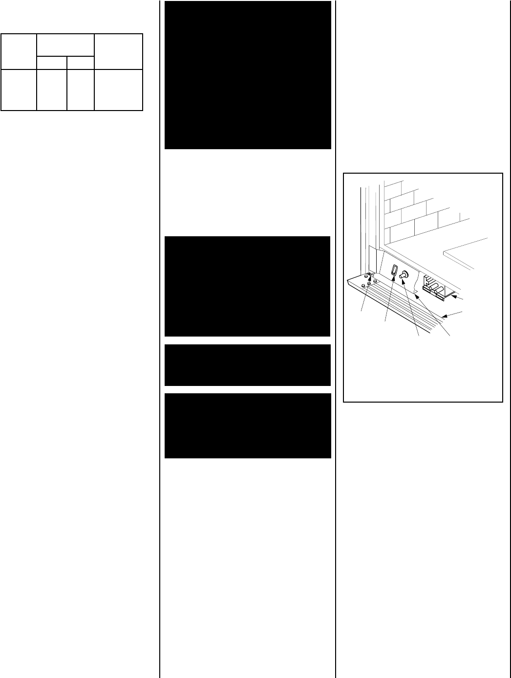
Figure 1
Control Compartment Access -
Millivolt Control Valve Shown
Piezo Ignitor
Gas Valve
Modesty Panel
Control
Compartment
Access panel
ON/OFF
Switch
Hinge Pin
Remove the bottom control compartment ac-
cess panel by compressing the spring-loaded
hinge pin on the left side until it disengages
from the left cabinet panel hole. Pull the panel
away from the fireplace.
Once the control compartment access panel
has been removed, the modesty panel can be
removed as follows: slide the modesty panel
forward until it contacts the cabinet bottom
panel, then lift straight up and tilt forward.
Remove the modesty panel carefully, so that
none of the wires become loose or discon-
nected. Now complete access to the gas control
valve and its related controls is attainable.
To ease door closure, depress the catches to
place them in their retracted position, then
close the door.
Operation of millivolt and electronic gas con-
trol systems are different. Before lighting and
operating your appliance determine if you
have a millivolt or electronic appliance.