


6
NOTE: DIAGRAMS & ILLUSTRATIONS NOT TO SCALE.
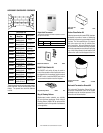
The adjustment rod, arm and associated adjust-
able air shutter is patented technology. Flame
adjustments can be made quickly and accurately
to taste without the need of disassembling the
appliance and waiting for 30 minutes after each
adjustment.
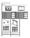
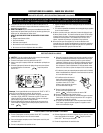
Front Glass Enclosure Panel, Removal
and Installation
These are direct-vent appliances. They are
designed to operate only when the front glass
enclosure panel is installed. Generally the front
glass enclosure panel should not be removed ex-
cept to gain access to the components within the
firebox, and the appliance may only be operated
without the front glass enclosure panel in place
for very brief periods of time during appliance
checkout and adjustment. Be sure that the flame
appearance will be diminished while the front
glass enclosure panel is removed.
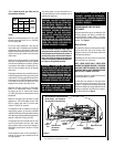
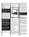
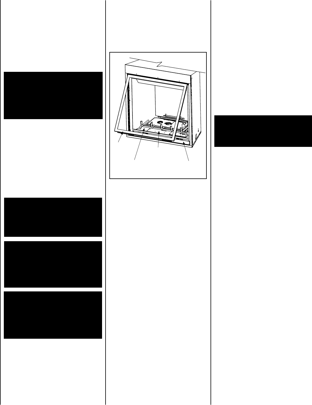
Refer to
Figure 4 and remove the front glass
enclosure panel as follows:
1.
Remove the bottom compartment door by
lifting and pulling it towards the front of the
fireplace.
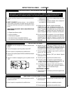
ENSURE THAT THE FRONT GLASS PANEL IS IN
PLACE AND SEALED DURING ADJUSTMENT.
Sooting is caused by incomplete combustion
in the flames and a lack of combustion air
entering the air shutter opening. To achieve a
warm yellow to orange flame with an orange
body that does not soot, the shutter opening
must be adjusted between these two extremes.
No smoke or soot should be present.
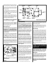
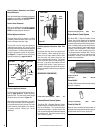
To adjust the flame, move the adjustment arm
(located in the lower control area) up or down
to increase or reduce the air shutter opening,
respectively. Position the air shutter to the
factory setting as shown in Figure 5 on page
7. Allow the burner to operate for at least 15
minutes. Observe the flame continuously. If it
appears weak or sooty as previously described,
adjust the air shutter by pushing or pulling on
the adjustment rod until the flame appearance
is as desired.
Figure 4
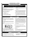
Burner Adjustments
The following paragraphs address burner
adjustment concerns and procedures.
When satisfied that the appliance operates
properly, proceed to finish the installation. Leave
the control knob in “ON” position and turn the
remote switch “OFF.” Close the lower control
compartment door.
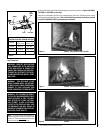
Flame Appearance and Sooting
Proper flame appearance is a matter of taste.
Generally most people prefer the warm glow of
a yellow to orange flame. Appliances operated
with air shutter openings that are too large will
exhibit flames that are blue and transparent.
These weak, blue and transparent flames are
termed anemic. If the air shutter opening is too
small sooting may develop.
Propane models may exhibit a flame pattern
that may candle or appear stringy. If this is
problematic or persists as the appliance is
continually operated, adjust the air shutter
closed as described in the previous paragraphs.
Operate the appliance for a period of time as the
effect diminishes, ensuring that the appliance
does not develop sooty flames.
Burner Adjustment
If the logs are properly positioned and sooting
conditions exist, the air shutter opening on the
main burner tube should be adjusted. Normally,
the more offsets in the vent system, the greater the
need for the air shutter to be opened further.
1.
Retrieve the glass door frame. Visually
inspect the gasket on the backside of the panel.
The gasket surface must be clean, free of ir-
regularities and seated firmly.
2. Position the door frame in front of the firebox
opening and engage the top flange over the lip
at the top of the firebox opening.
3. Swing the door down and back. Ensure the
gasket seats evenly as the door draws shut. Engage
the Vee-flange at the bottom of the door with the
latches and close the latches to secure the door.
4.
Reinstall the bottom compartment door by hook-
ing it over the slots on the two corner posts.
To install the front glass enclosure panel,
proceed as follows:
CAUTION: THE ADJUSTMENT ARM AND
NEARBY APPLIANCE SURFACES ARE HOT.
EXERCISE CAUTION TO AVOID INJURY WHILE
ADJUSTING FLAME APPEARANCE.
WARNING: DO NOT OPERATE AP-
PLIANCE WITH THE GLASS FRONT
REMOVED, CRACKED OR BROKEN.
REPLACEMENT OF THE GLASS SHOULD
BE DONE BY A LICENSED OR QUALIFIED
SERVICE TECHNICIAN.
WARNING: HANDLE THIS GLASS WITH EX-
TREME CARE! TEMPERED GLASS IS SUS-
CEPTIBLE TO DAMAGE – DO NOT SCRATCH
OR HANDLE ROUGHLY WHILE REINSTALL-
ING THE GLASS DOOR FRAME.
WARNING: NO NOT ATTEMPT TO SUB-
STITUTE THE MATERIALS USED ON
THIS DOOR, OR REPLACE CRACKED OR
BROKEN GLASS WITH ANY MATERIALS
OTHER THAN THOSE PROVIDED BY THE
APPLIANCE MANUFACTURER.
THE GLASS DOOR OF THIS APPLI-
ANCE MUST ONLY BE REPLACED AS A
COMPLETE UNIT AS PROVIDED BY THE
MANUFACTURER. DO NOT ATTEMPT
TO REPLACE BROKEN, CRACKED OR
CHIPPED GLASS SEPARATELY.
WARNING: AIR SHUTTER ADJUSTMENT
SHOULD ONLY BE PERFORMED BY A
QUALIFIED PROFESSIONAL SERVICE
TECHNICIAN.
Door
Assembly
Gas Line Access Panel
Bottom Panel
Blower Access
Plate
Sooting is indicated by black puffs developing
at the tips of very long orange flames. Sooting
results in black deposits forming on the logs,
appliance inside surfaces and on exterior sur-
faces adjacent to the vent termination.
2. Locate the two (2) latches at the top of the
control compartment and disengage them from
the floor frame bottom Vee-flange, pulling down
on their handles to open them.
3. Swing the bottom of the door out and raise
it slightly to lift the top flange of the door frame
away from the appliance.
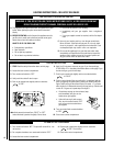
Refer to the maintenance schedule for mainte-
nance tasks, procedures, periodicity and by whom
they should be performed. Always verify proper
operation of the appliance after servicing.
IMPORTANT: TURN OFF GAS AND ANY
ELECTRICAL POWER BEFORE SERVICING
THE APPLIANCE.