


7
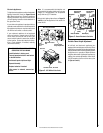
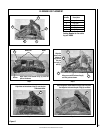
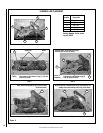
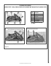
NOTE: DIAGRAMS & ILLUSTRATIONS ARE NOT TO SCALE.
Orifice Sizes - Sea Level to High Altitude
(All Models): These appliances are tested and
approved for installations at elevations of 0-4500
feet (0-1372 meters) above sea level using the
standard burner orifice sizes (marked with an
"*" in Table 4).
For higher elevations, contact your gas supplier
or qualified service technician.
Install the appliance according to the regulations
of the local authorities having jurisdiction and,
in the USA, the National Fuel Gas Code NFPA
54 / ANSI Z223.1 - latest edition or, in Canada,
the CAN/CSA-B149.1- latest edition.
Deration -
At higher elevations, the amount of BTU fuel
value delivered must be reduced by either
using gas that has been derated by the gas
company or by changing the burner orifice to a
smaller size as regulated by the local authorities
having jurisdiction and by the (USA) National
Fuel Gas Code NFPA 54/ANSI Z223.1 - latest
edition or, in Canada, the CAN/CSA-B149.1 -
latest edition.
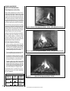
Burn-in Period
During the first few fires of this appliance there
will be some odor due to the curing of the
paint and burning off of lubricants used in the
manufacturing process. Depending on your
use, the burn-in period may take a few hours
or a few days.
KEEP YOUR HOUSE WELL VENTILATED
DURING THE CURING PROCESS. THE ODOR
AND HAZE EMITTED DURING THE CURING
PROCESS CAN BE QUITE NOTICEABLE AND
MAY SET OFF A SMOKE DETECTOR.
If an optional blower is installed, Do Not turn
it on during the Burn-In period.
A white film may develop on the glass front
during the first few fires as part of the curing
process. The glass should be kept clean during
the first two weeks of use to prevent the film from
baking on (making it very difficult to remove).
See Cleaning Glass on Page 10.
Gas Pressure
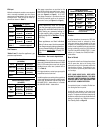
Tables 2 and 3 show the appliances' gas
pressure requirements.
Inlet Gas Supply Pressure
(all models)
Fuel # Minimum Maximum
Natural Gas
4.5" WC
(1.12 kPa)
10.5" WC
(2.61 kPa)
Propane
11.0" WC
(2.74 kPa)
13.0" WC
(3.23 kPa)
Table 2
Manifold Gas Supply Pressure
(all models)
Fuel # Low High
Natural
Gas
(Lo) 2.2" WC
(0.55 kPa)
(Hi) 3.5" WC
(0.87 kPa)
Propane
(Lo) 6.3" WC
(1.57 kPa)
(Hi) 10.0" WC
(2.49 kPa)
Table 3
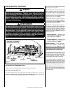
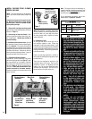
Test gauge connections are provided on the
front of the millivolt gas control valve, identi-
fied IN for the inlet and OUT for the manifold
side (see Figure 2 on Page 9). A 1/8" NPT
Test gauge connection is provided at the inlet
and outlet (manifold) ports on the electronic
gas control valve (see Figure 3 on Page 9).
BTU Input
Millivolt and electronic models come standard
with a manually-modulated gas valve; flame
appearance and heat output can be controlled
at the gas valve. The BTU Input for these ap-
pliances are shown in Table 1.
These appliances must be isolated
from the gas supply piping system (by
closing their individual manual shut-off
valve) during any pressure testing of
the gas supply piping system at test
pressures equal to or less than 1/2 psig
(3.5 kPa).
These appliances and their individual
shut-off valves must be disconnected
from the gas supply piping system dur-
ing any pressure testing of that system
at pressures greater than 1/2 psig (3.5
kPa).
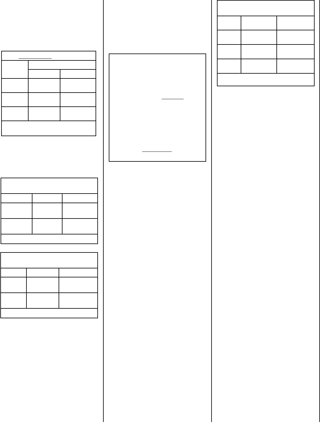
Burner Orifice Sizes
Elevation 0-4500 feet ( 0-1372 meters)
Model
Series
Nat.Gas
drill size (inches)
Propane
drill size (inches)
ELDV35
#38 (0.1015")*
99K76•
#53 (0.0595")*
39L10•
ELDV40
#37 (0.1040")*
24M10•
(0.062")*
21L01•
ELDV45
#36 (0.1065")*
74L88•
#52 (0.0635")*
80L41•
Table 4
* Standard size installed at factory
• Part /Cat. Number
Input (BTU/HR) (all models)
Models
Input Rate (BTU / HR)
Natural Gas Propane Gas*
ELDV35
27,000 high
21,000 low
26,000 high
20,000 low
ELDV40
29,000 high
23,000 low
27,000 high
22,000 low
ELDV45
30,000 high
23,000 low
28,000 high
21,000 low
Table 1
*Electronic valves may be
converted to propane.