


17
NOTE: DIAGRAMS & ILLUSTRATIONS ARE NOT TO SCALE.
WARNINGS
• Air shutter adjustment should
only be performed by a quali-
fied professional service
technician.
• Ensure front glass panel are
in place and sealed during
adjustment.
CAUTIONS
• Carbon will be produced if the
air shutter is closed too much.
Any damage due to carboning
resulting from improperly
setting the air shutter is not
covered under the warranty.
• The air shutter door and nearby
appliance surfaces are hot.
Exercise caution to avoid
injury while adjusting flame
appearance.
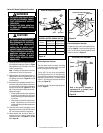
Burner Air Shutter Adjustment Procedure
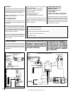
Electronic Appliance Checkout
To light the burner, refer to the lighting instruc-
tions on Page 24. Ensure the igniter lights the
pilot. The pilot flame should engulf the flame
sensor as shown in Figure 16.
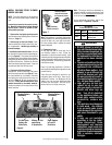
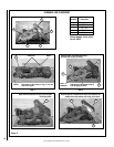
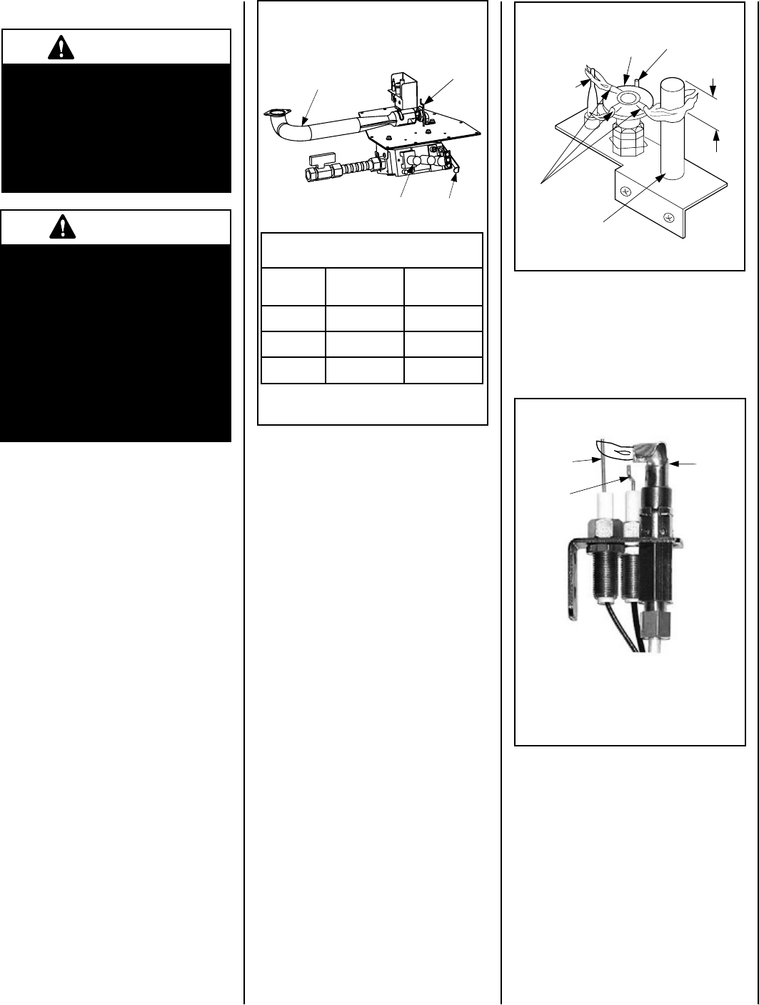
ELECTRONIC PILOT ASSEMBLY
Thermocouple
Thermopile
Pilot
Nozzels
SIT MILLIVOLT PILOT ASSEMBLY
3/8" Min.
(9 mm)
Igniter Rod
Pilot Hood
Proper Pilot Flame Appearance
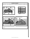
Millivolt Appliance Checkout
The pilot flame should be steady, not lifting
or floating. Flame should be blue in color with
traces of orange at the outer edge.
The top 3/8" (10 mm) at the pilot generator
(thermopile) and the top 1/8" minimum (tip)
of the quick drop out thermocouple should be
engulfed in the pilot flame. The flame should
project 1" (25 mm) beyond the hood at all three
ports (see Figure 15).
To light the burner, refer to the lighting instruc-
tions on Page 22.
Figure 15
Note: If the igniter is damaged, a
replacement kit is available, order
Catalog Number 87L54.
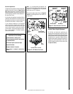
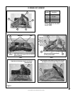
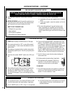
1. Locate adjustment rod and adjust air shutter
to the standard setting as shown in Figure
14 (adjustment rod is located in the lower
control compartment).
Note: Rotating the adjustment rod down
to decrease air and up to increase air.
2. Light appliance (follow lighting procedure on
lighting label in control compartment or see
the lighting instructions, Pages 22 and 24
in this manual).
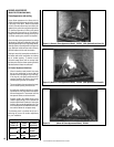
3. Allow the burner to operate for at least 15 min-
utes while observing the flame continuously
to ensure that the proper flame appearance
has been achieved (see Figures 11, 12 or
13). If the following conditions are present,
adjust accordingly.
• Ifameappearsweakorsooty,adjustthe
air shutter, incrementally, to a more open
position until the proper flame appearance
is achieved.
• Ifamestaysloweredblue,adjusttheair
shutter, incrementally, to a more closed
position until the proper flame appearance
is achieved.
4. Leave the control knob (off/pilot/on) in the
ON position and the burner OFF/ON switch
OFF (and remote switches, if applicable).
5. When satisfied that the burner flame ap-
pearance is normal, close the lower control
compartment door (see Figures 11, 12 and
13 on Page 16).
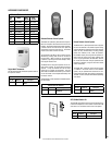
ELECTRONIC
Pilot
Hood
Sensor
Igniter
Burner Air Shutter Adjustment
Figure 14
Figure 16
Venturi
Air
Shutter
Rod
Valve
Lever Arm
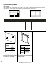
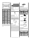
RENRUBNIAM
GNITTESGNINEPORETTUHSYROTCAF
sledoM
saGlarutaN
)mm(sehcni
saGenaporP
)mm(sehcni
53VDLE8/1)2.3(8/3)5.9(
04VDLE)4.6(4/1)1.11(61/7
54VDLE)4.6(4/1)1.11(61/7